Personal robotic system and method

a robotic system and robotic method technology, applied in the field of personal robotic systems, can solve the problems that neither of these personal robotic systems, nor the others that are available, are well suited to operating in human environments such as elderly care facilities, hotels, hospitals, etc., to achieve automatic minimizing destabilizing moments, controlling nearby objects, and minimizing destabilizing moments

Inactive Publication Date: 2016-07-21
WILLOW GARAGE
View PDF0 Cites 35 Cited by
  • Summary
  • Abstract
  • Description
  • Claims
  • Application Information

AI Technical Summary

Benefits of technology

[0009]One embodiment is directed to a personal robotic system, comprising: an electromechanical mobile base configured to be controllably movable upon a substantially planar surface in a global coordinate system wherein a Z axis is defined perpendicular to the substantially planar surface; a torso assembly movably coupled to the mobile base such that the torso may be controllably moved in a direction substantially parallel to the Z axis and also controllably rotated about an axis substantially perpendicular to the Z axis; a head assembly movably coupled to the torso assembly; a robotic arm operatively coupled to the torso assembly; and a controller operatively coupled to the mobile base, torso assembly, head assembly, and robotic arm, and configured to controllably manipulate nearby objects while also automatically minimizing destabilizing moments applied to the mobile base through movement of at least one of the mobile base, torso assembly, head assembly, and robotic arm. The system further may comprise a sensor operatively coupled to the controller and configured to sense one or more factors regarding an environment in which the mobile base is navigated. The sensor may comprise a sonar sensor. The sonar sensor may be coupled to the mobile base. The sensor may comprise a laser range finder. The sonar sensor may be coupled to the mobile base. The sensor may comprise an image capture device. The image capture device may comprise a 3-D camera. The image capture device may be coupled to the head assembly. The image capture device may be coupled to the mobile base. The image capture device may be coupled to the torso assembly. The mobile base may comprise a differential drive configuration having two driven wheels. Each of the driven wheels may be operatively coupled to an encoder that is operatively coupled to the controller and configured to provide the controller with input information regarding a driven wheel position. The controller may be configured to operate the driven wheels to navigate the mobile base based at least in part upon the input information from the driven wheel encoders. The controller may be configured to operate the mobile base based at least in part upon signals from the sensor. The torso assembly may be movably coupled to the mobile base such that the torso may be controllably elevated and lowered along an axis substantially parallel to the Z axis. The head assembly may comprise an image capture device. The image capture device may comprise a 3-D camera. The image capture device may be movably coupled to the head assembly such that it may be controllably panned or tilted relative to the head assembly. The robotic arm may comprise a non-electromechanical gravity compensation subsystem. The gravity compensation subsystem may comprise an at least partially compressed spring. The gravity compensation subsystem may be configured such that a load from the least partially compressed spring substantially counterbalances a gravitational load on the robotic arm. The controller may be configured to minimize destabilizing moments applied to the mobile base based at least in part upon one or more loads applied to the robotic arm. The controller may be configured to detect one or more loads based upon currents detected in one or more motors operatively coupled to the robotic arm. The system further may comprise a sensor configured to produce a signal correlated with a load applied to the robotic arm. The system may comprise a sensing element selected from the group consisting of a strain gauge, a piezoelectric crystal, a ferromagnetic element, a Bragg grating, an accelerometer, and a gyro. The system further may comprise a wireless transceiver configured to enable a teleoperating operator to remotely connect with the controller from a remote workstation, and to operate at least the mobile base.

Problems solved by technology

Personal robots, such as those available under the tradenames Roomba® and PR2® by suppliers such as iRobot® and Willow Garage®, respectively, have been utilized in human environments to assist with human-scale tasks such as vacuuming and grasping various items, but neither of these personal robotic systems, nor others that are available, are well suited for operating in human environments such as elderly care facilities, hotels, or hospitals in a manner wherein they may be utilized to manipulate human-scale objects around using an efficient footprint with enhanced stability and range of motion and manipulation reach.

Method used


Image

  • Personal robotic system and method
  • Personal robotic system and method
  • Personal robotic system and method

Examples


Embodiment Construction

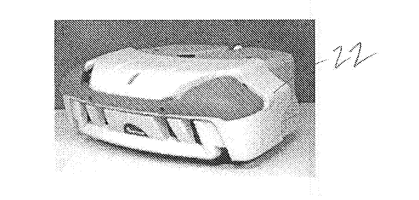
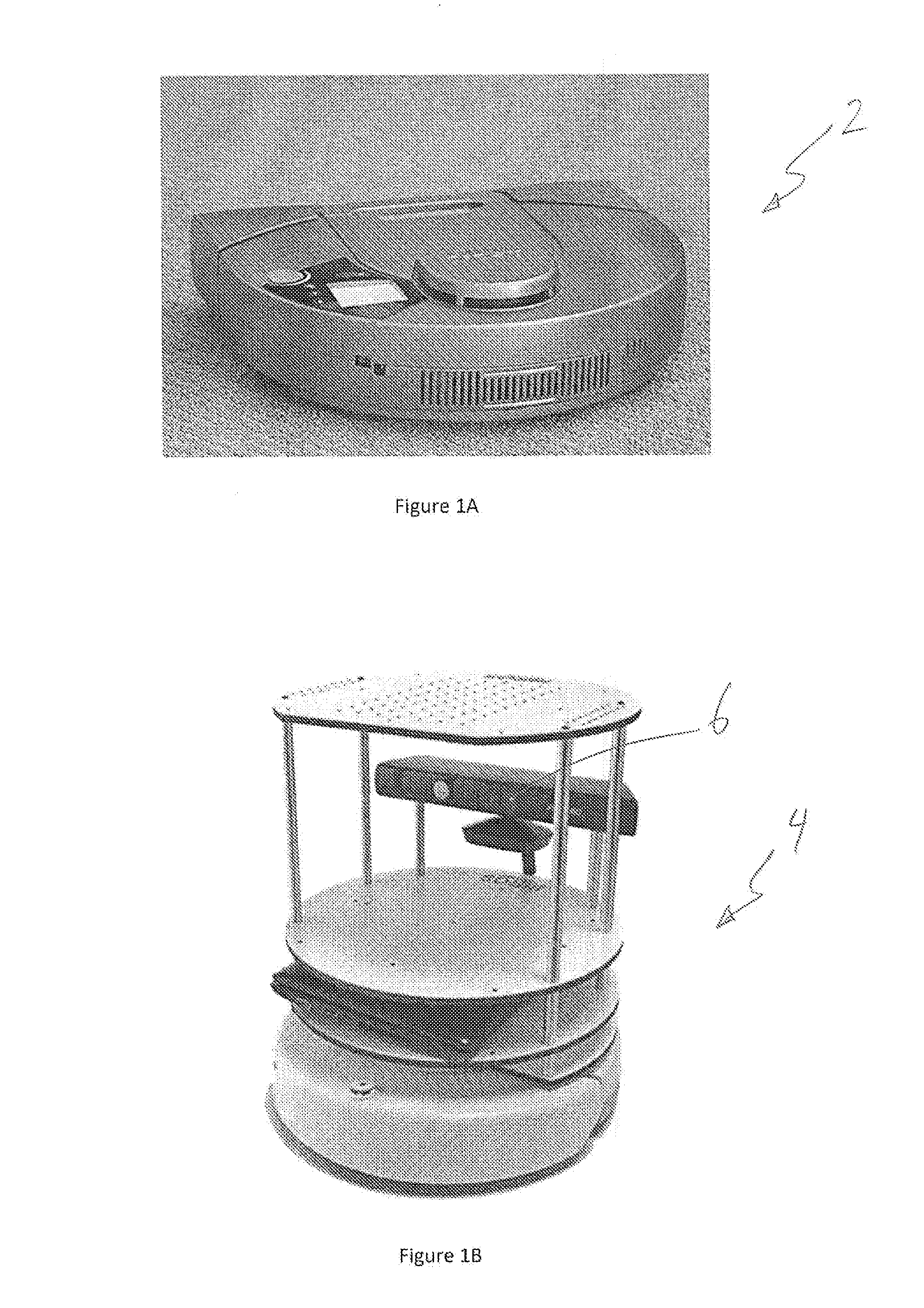
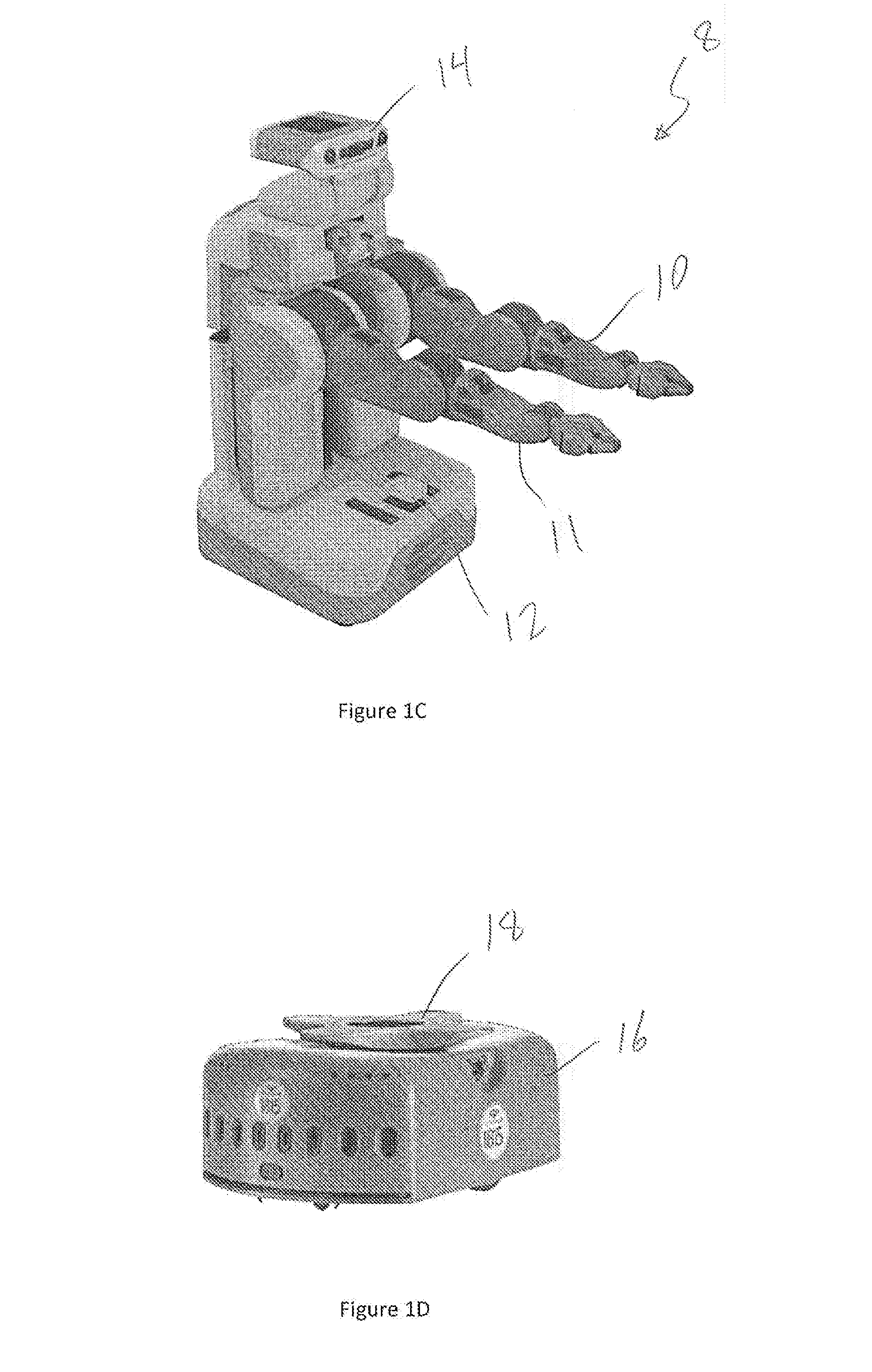
[0011]Referring to FIG. 1A, a vacuuming robot (2) is depicted which has primary function for vacuuming floors in a human environment, and has little other utility due to its design. FIG. 1B illustrates a lightweight robotics platform (4) sold under the tradename “turtlebot”® by Willow Garage, Inc., which features a 3-D camera, such as those available under the tradename Kinect® from Microsoft Corp. Such a platform may be programmed to handle light duty tasks, such as moving around a plate or two, or some lightweight tools or food. FIG. 1C illustrates a heavier duty personal robotics platform (8) sold under the tradename “PR2” by Willow Garage, Inc. This platform features two sophisticated arms (10, 11), a multi-sensor head (14), and a laser scanner (12) coupled to the mobile base component and is capable of conducting certain human-scale tasks, but is not optimized for handling inventory or bin management exercises. FIG. 1D features a small robotic system (16) sold by Kiva, Inc., wh...


PUM


Abstract

One embodiment is directed to a personal robotic system, comprising: an electromechanical mobile base configured to be controllably movable upon a substantially planar surface in a global coordinate system wherein a Z axis is defined perpendicular to the substantially planar surface; a torso assembly movably coupled to the mobile base such that the torso may be controllably moved in a direction substantially parallel to the Z axis and also controllably rotated about an axis substantially perpendicular to the Z axis; a head assembly movably coupled to the torso assembly; a robotic arm operatively coupled to the torso assembly; and a controller operatively coupled to the mobile base, torso assembly, head assembly, and robotic arm, and configured to controllably manipulate nearby objects while also automatically minimizing destabilizing moments applied to the mobile base through movement of at least one of the mobile base, torso assembly, head assembly, and robotic arm.

Description

RELATED APPLICATION DATA[0001]The present application is a continuation of U.S. patent application Ser. No. 14 / 826,415, filed on Aug. 14, 2015, which is a continuation of U.S. patent application Ser. No. 14 / 584,158, filed on Dec. 29, 2014, which claims the benefit under 35 U.S.C. §119 to U.S. Provisional Application Ser. No. 61 / 921,673 filed Dec. 30, 2013. The foregoing applications are hereby incorporated by reference into the present application in their entirety.FIELD OF THE INVENTION[0002]The present invention relates generally to robotic systems for use in human environments, and more particularly to automated and semiautomated systems for assisting in the manipulation of human scale objects using an electromechanically movable base.BACKGROUND[0003]Personal robots, such as those available under the tradenames Roomba® and PR2® by suppliers such as iRobot® and Willow Garage®, respectively, have been utilized in human environments to assist with human-scale tasks such as vacuuming...

Claims


Application Information

Patent Timeline
Patent Type & Authority Applications(United States)
IPC IPC(8): B25J5/00G05D1/02B25J9/00G05D1/00B25J9/16B65G1/137
CPCB25J5/007B25J9/1689B65G1/137B25J9/1697Y10S901/46G05D1/0022G05D1/0251Y10S901/01Y10S901/47B25J9/0003B25J19/0016B25J19/021B25J19/026G05D2201/0216B25J9/162B25J9/1638B25J9/04G05D1/0094G05D1/021
Inventor WISE, MELONEE
Owner WILLOW GARAGE
Why Eureka
Try Eureka