Inspection method of liquid discharge head and liquid discharge device

a liquid discharge device and liquid discharge technology, applied in the direction of printing, other printing apparatus, etc., can solve the problems of higher possibility of separation, and difficult detection of separation, so as to reduce useless consumption of liquid, reduce processing time accordingly, and reliably detect the separation of a member

Active Publication Date: 2016-07-21
SEIKO EPSON CORP
View PDF0 Cites 12 Cited by
  • Summary
  • Abstract
  • Description
  • Claims
  • Application Information

AI Technical Summary

Benefits of technology

[0009]According to the configuration described above, separation of a member joined to the partition wall is detected based on the first driving step of driving a first actuator corresponding to an inspection target nozzle, the first detection step of detecting vibration that is generated in liquid in a pressure chamber corresponding to the inspection target nozzle by the driving in the first driving step, the second driving step of driving together the first actuator and a second actuator corresponding to at least one nozzle of nozzles adjacent to the inspection target nozzle, the second detection step of detecting vibration that is generated in the liquid in the pressure chamber corresponding to the inspection target nozzle by the driving in the second driving step, and the difference between a detection result of the first detection step and a detection result of the second detection step. Therefore, it is possible to more reliably detect the separation of a member, which has been difficult to detect separately from a trouble of discharge due to thickening. In the configuration described above, it is preferable that the inspection processing is performed when an accumulated load related to generation of the separation exceeds a predetermined determination value.
[0010]According to this configuration, the inspection processing is performed when the accumulated load related to the generation of the separation exceed a predetermined determination value, so that it is possible not to perform the inspection processing in an initial stage in which the possibility of the generation of the separation is relatively small. Therefore, it is possible to reduce the processing time accordingly. Further, when liquid is discharged from the nozzles in the inspection processing, it is possible to reduce useless consumption of the liquid.

Problems solved by technology

When the adhesive degrades and separation between members occurs, in particular, when vertical separation occurs in a partition wall that partitions the pressure chamber, there is a risk that problems occur, such as liquid leaks from a separated portion and liquid is not normally discharged from nozzles because pressure loss occurs when the liquid is discharged.
However, there is a problem that when separation or the like occurs due to aging or the like, it is difficult to detect the separation as distinguished from the trouble in discharging liquid due to thickening of the liquid or the like.
On the other hand, the greater the accumulated load, the higher the possibility of generation of separation.
According to this configuration, the smaller the accumulated load, the smaller the possibility that a separation occurs, so that false detection is suppressed by setting a relatively large allowable error in determination of separation in the separation detection step.

Method used


Image

  • Inspection method of liquid discharge head and liquid discharge device
  • Inspection method of liquid discharge head and liquid discharge device
  • Inspection method of liquid discharge head and liquid discharge device

Examples


Embodiment Construction

[0034]Hereinafter, a first embodiment for implementing the invention will be described with reference to the attached drawings. In the embodiments described below, various limitations are imposed as preferable specific examples. However, the scope of the invention is not limited to the embodiments unless there is a particular description to limit the invention in the following description. Hereinafter, as a liquid discharge device of the invention, an ink jet type recording device (hereinafter, printer) will be described as an example.

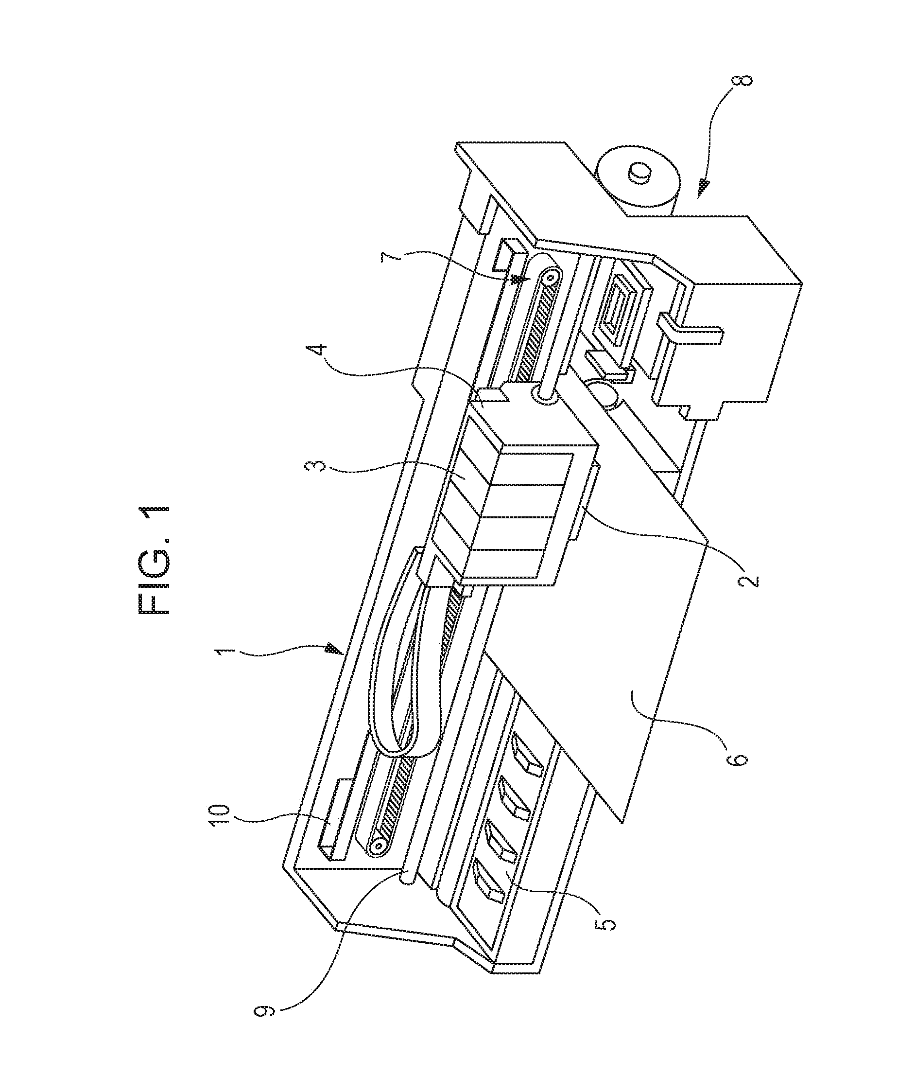
[0035]FIG. 1 is a perspective view showing a configuration of a printer 1. The printer 1 is roughly composed of a carriage 4 to which a recording head 2 that is a kind of a liquid discharge head is attached and to which an ink cartridge 3 that is a kind of a liquid supply source is attachably and detachably attached, a platen 5 arranged below the recording head 2 which is performing a recording operation, a carriage moving mechanism 7 that reciprocates...


PUM


Abstract

Inspection processing is performed. The inspection processing includes a first driving step of driving a piezoelectric element corresponding to an inspection target nozzle, a first detection step of detecting vibration that is generated in ink in a pressure chamber corresponding to the inspection target nozzle by the driving in the first driving step, a second driving step of driving together the piezoelectric element corresponding to the inspection target nozzle and a piezoelectric element corresponding to at least one nozzle of nozzles adjacent to the inspection target nozzle, and a second detection step of detecting vibration that is generated in the ink in the pressure chamber corresponding to the inspection target nozzle by the driving in the second driving step.

Description

BACKGROUND[0001]1. Technical Field[0002]The present invention relates to an inspection method of a liquid discharge head such as an ink jet type recording head and a liquid discharge device, in particular to an inspection method of a liquid discharge head that discharge liquid from nozzles by generating pressure vibration in liquid in pressure chambers connected to the nozzles by driving of actuators and a liquid discharge device.[0003]2. Related Art[0004]The liquid discharge device is a device which includes a liquid discharge head that can discharge liquid as droplets from nozzles and discharges various liquids from the liquid discharge head. A typical example of the liquid discharge device is an image recording device such as an ink jet type recording device (printer) which includes an ink jet type recording head (hereinafter referred to as a recording head) and performs recording by discharging liquid ink as droplets from nozzles of the recording head. Further, a liquid discharg...

Claims


Application Information

Patent Timeline
Patent Type & Authority Applications(United States)
IPC IPC(8): B41J29/393
CPCB41J2/0451B41J29/393B41J2/04581B41J2/04588B41J2/04596B41J29/38B41J2002/14354
Inventor TAKANO, KOJIFUKUDA, MASAKOSUZUKI, TOSHIYUKISHIMIZU, SATOSHI
Owner SEIKO EPSON CORP
Why Eureka
Try Eureka