Adjustable umbrella base

a technology of umbrella base and adjustable bracket, which is applied in the direction of umbrellas, machine supports, other domestic objects, etc., can solve the problems of affecting the enjoyment of the activity of participants and significant inconvenien

Active Publication Date: 2016-07-21
NGU HAO THU
View PDF1 Cites 7 Cited by
  • Summary
  • Abstract
  • Description
  • Claims
  • Application Information

AI Technical Summary

Benefits of technology

[0004]In one embodiment, an umbrella stand includes a receptacle for receiving a portion of a mast of an umbrella, and a base portion configured to interface with a ground surface. A movable joint is disposed between the receptacle and the base portion. A frictional force present between components of the movable joint is great enough to maintain a position of the receptacle relative to the base portion under the weight of the umbrella and mast, and is small enough that the receptacle can be repositioned relative to the base portion by application of a manual force to the mast of the umbrella.

Problems solved by technology

This may create significant inconvenience and potentially interrupt the participants' enjoyment of the activity.

Method used


Image

  • Adjustable umbrella base
  • Adjustable umbrella base
  • Adjustable umbrella base

Examples


Embodiment Construction

[0010]The illustrations presented herein are not meant to be actual views of any particular device, but are merely idealized representations, which are employed to describe example embodiments of the present disclosure.

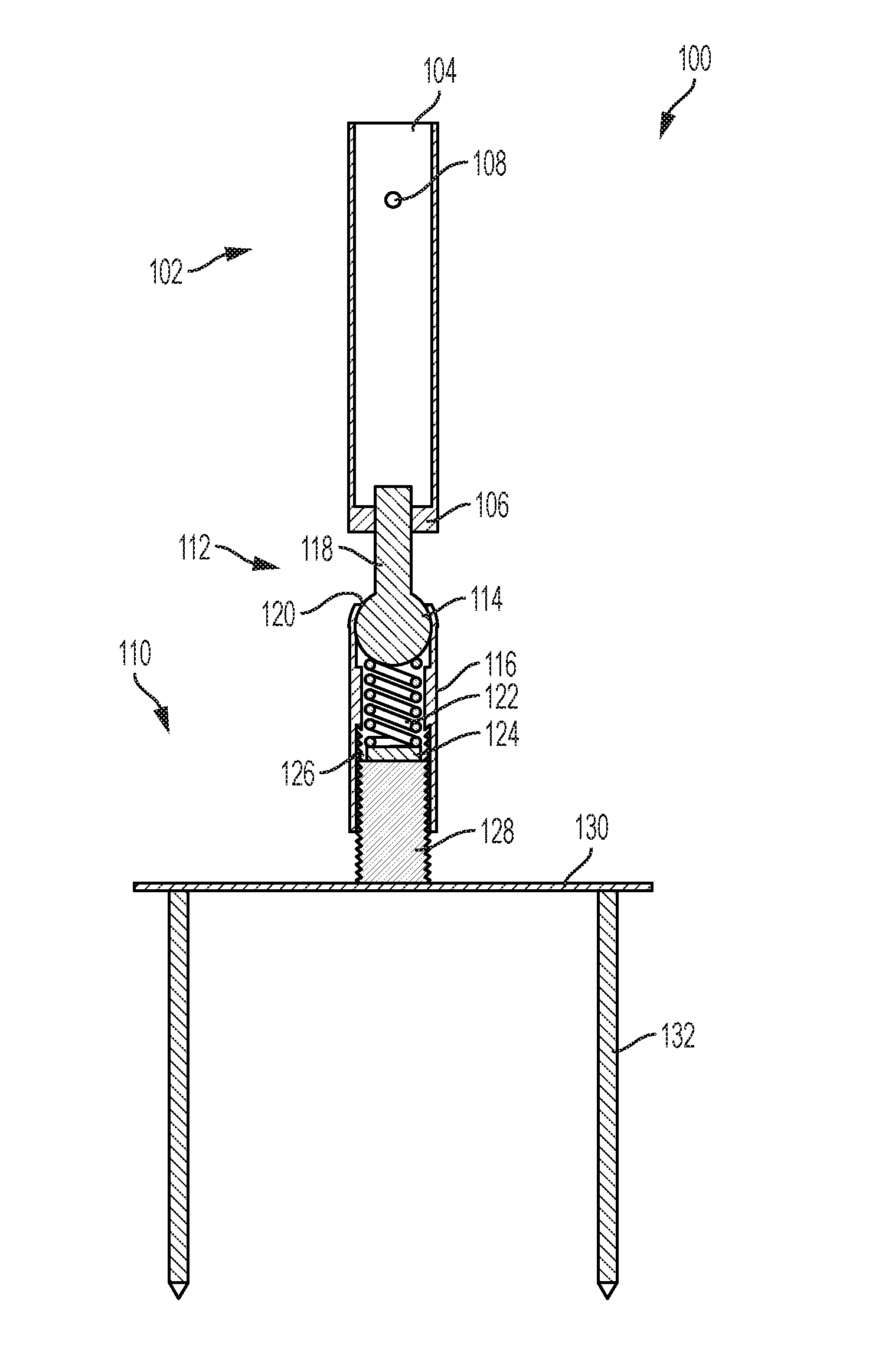
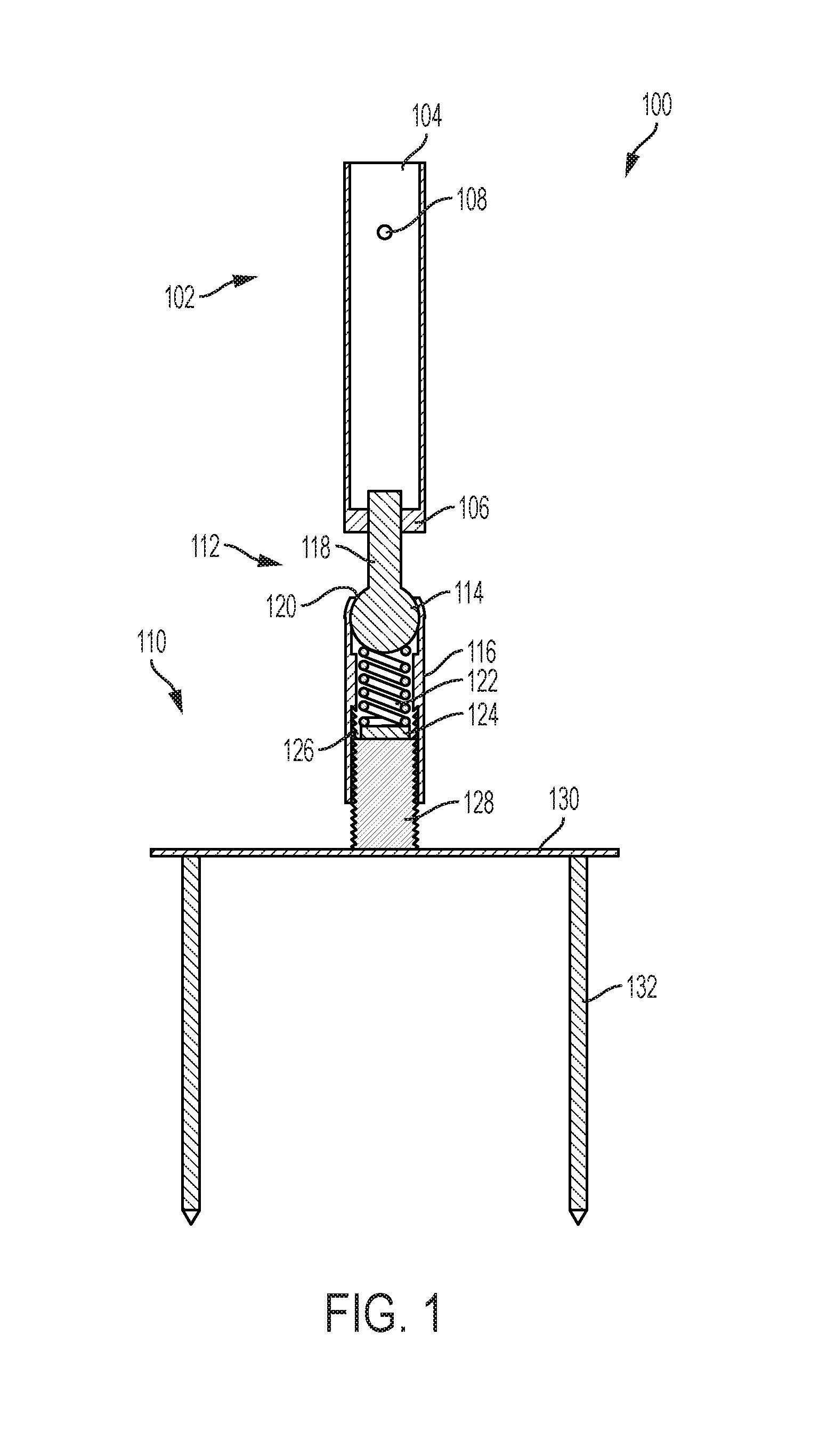
[0011]FIG. 1 is a cross-sectional view of an adjustable umbrella stand 100 according to the present disclosure. The adjustable umbrella stand 100 may include a receptacle 102 configured to support a mast of an umbrella (not shown). The receptacle 102 may have any suitable configuration for retaining (e.g., gripping, holding) the umbrella mast. For example, as shown in FIG. 1, the receptacle 102 may have a tubular shape with an open end 104 and a closed end 106. An end portion of the umbrella mast may be placed in the open end 104 and inserted until the end portion of the mast rests upon the interior of the closed end 106 of the receptacle 102. The mast may be retained within the receptacle by tightening a set screw (e.g., wing bolt) within a set screw bore 108. The re...


PUM


Abstract

An umbrella stand may include a receptacle for receiving a portion of a mast of an umbrella and a base portion configured to interface with a ground surface. A movable joint is disposed between the receptacle and the base portion. A frictional force present between components of the movable joint is great enough to maintain a position of the receptacle relative to the base portion under the weight of the umbrella and mast, and is small enough that the receptacle can be repositioned relative to the base portion by application of a manual force to the mast of the umbrella. The movable joint may be lockable into different positions.

Description

PRIORITY CLAIM[0001]This application is a continuation-in-part of U.S. patent application Ser. No. 15 / 000,229, filed Jan. 19, 2016, for “Adjustable Umbrella Base,” pending, which is a utility conversion of U.S. Provisional Patent Application Ser. No. 62 / 105,491, filed Jan. 20, 2015, the disclosure of each of which is hereby incorporated herein in its entirety by this reference.TECHNICAL FIELD[0002]Embodiments of the present disclosure relate generally to stands for umbrellas.BACKGROUND[0003]Temporary shade from the sun, or protection from rain or snow, may be needed for spectators or other participants in situations such as outdoor recreational activities like sports games, outdoor concerts, etc. Such protection may be provided by an umbrella including, for example, a fabric canopy supported by a folding frame of metal or polymer spars. The folding frame may be connected to a mast, and the mast may be retained in a stationary stand placed on or in the ground. As the angle of the sun...

Claims


Application Information

Patent Timeline
Patent Type & Authority Applications(United States)
IPC IPC(8): E04H12/22A45F3/44F16M11/14
CPCE04H12/2284E04H12/2238A45B2200/109A45F3/44F16M11/14A45B17/00A45B2017/005A45B2023/0012F16M2200/041E04H12/2215
Inventor NGU, HAO THU
Owner NGU HAO THU
Why Eureka
Try Eureka