
Communications cable and method of making same

a technology of communication cable and fiber optic cable, which is applied in the field of communication cable, can solve the problems of unusable signal after 3000 feet, fiber optic cable using multi-mode fiber typically having distance limitations, and creating a much greater threat of damage to multi-mode fiber optic cables, etc., and achieves the effects of enhancing promoting combustibles or air circulation, and promoting longitudinal force or tensile strength

Inactive Publication Date: 2016-07-21
TECH MINING COMPANY
View PDF9 Cites 0 Cited by
  • Summary
  • Abstract
  • Description
  • Claims
  • Application Information

AI Technical Summary

Benefits of technology

The present communication cable and method provide a high temperature duplex optical fiber system that can operate over a wider range of temperatures than current cables. The cable has a duplex 50 μm x 125 μm multi-mode fiber optic cable that can handle more mechanical forces at higher temperatures than conventional cables. The cable's design allows for a simple buffer tube, minimizing space when strength is not required.

Problems solved by technology

Multi-Mode Fiber Optic cables typically create much more threat of damage due to structural fires and the requirement to sustain significantly higher temperatures.
Fiber Optic cables using Multi-Mode fiber typically have distance limitations due to the optical carrying characteristics which degenerate optical signals to an unusable state either by attenuation or scrambling resulting in unusable signal after 3000 feet.
As such, their outer jacket material is required to not sustain or permit a migration of any fire when subjected to a flame either in a vertical Riser condition or in a horizontal air Plenum configuration.
Cables without this flame retardant additive typically can cause fire migration and are generally illegal by local and National building codes.
Teflon type jackets typically start to burn or melt at 600 degrees Fahrenheit.
In comparison, the reduced overall diameter of Single mode fiber is only 9 μm in diameter and therefore significantly more susceptible to physical damage.
This antique classification for heat ratings of cables has been shown to repeatedly be ineffectual in building communications systems when fires threaten any area, thereby cutting off any communications path offered by these type cables.
This historically makes fiber optic cable much more prone to failure then their copper counterparts.
Applicant realized that a solution begins with the glass used in these cables and notoriously this type of high temperature glass and its associated high cost makes the normal solution almost unaffordable or unattainable.

Method used


Image

  • Communications cable and method of making same
  • Communications cable and method of making same
  • Communications cable and method of making same

Examples


Embodiment Construction

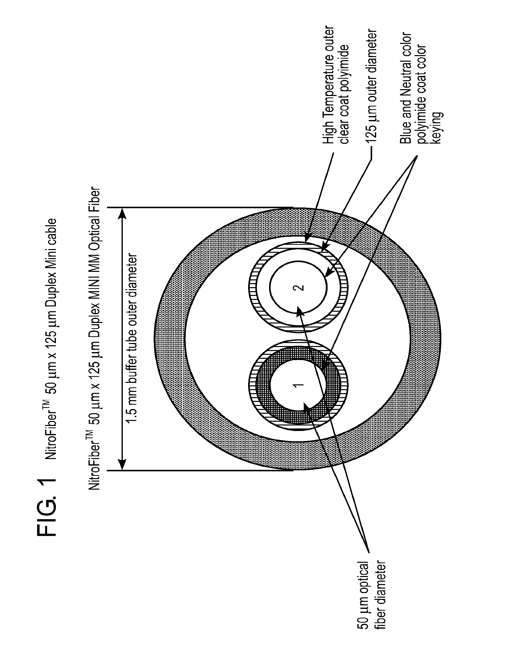
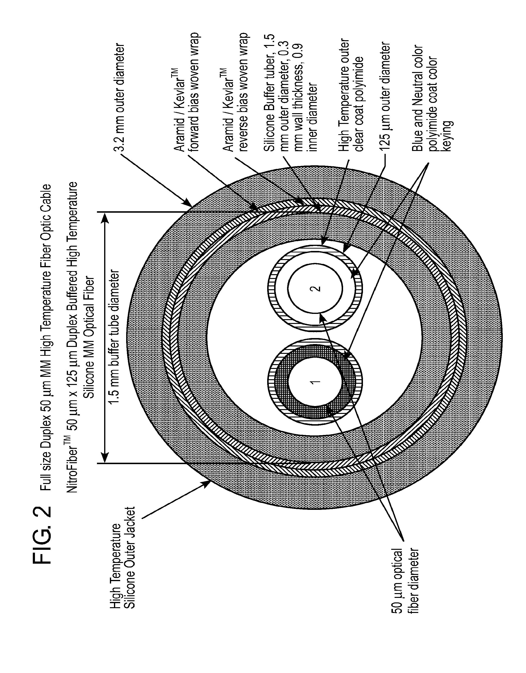
[0024]In the preferred embodiment of the present communications cable and method for making same, a high temperature optical glass is provided that is capable of withstanding temperatures in excess of the 800 degree Fahrenheit range. Preferably, 2-50 μm×125 μm Multi-Mode fibers are both color coated and mechanically protect with a similarly high temperature polyimide plastic bring the overall diameter to 125 μm and leaving Buffer colors of Natural, and Blue for easy polarity identification. In the Quad design grouping additional Yellow and Red colors are used for further easy identification.

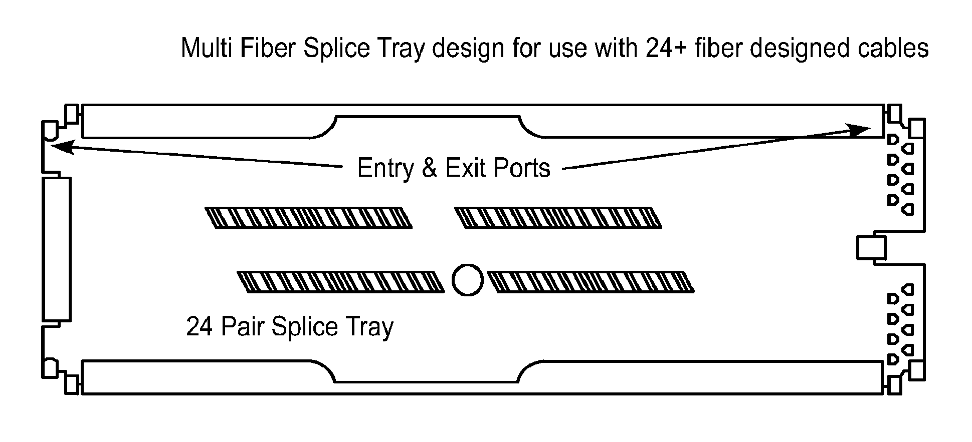
[0025]As shown in FIGS. 1-3, in a first step, preferably two and up to four optical fibers are placed within a high temperature protective silicone rubber buffer tube, to enhance their thermal handling properties. As shown in FIG. 1, this silicone rubber buffer tube is preferably approximately 1 millimeter in outside diameter.

[0026]In FIG. 1, the nature of the product at this stage with its therm...


PUM


Abstract

A communications cable and method for making same wherein a communications cable is able to withstand significantly higher thermal temperatures than conventional fiber whether it be general purpose, or rated as Plenum / Riser rating, or even MIL Spec type cables. A core fiber glass material with at least an 800 Fahrenheit degree operating ability allows the communications cable to survive in high heat or stress conditions. A polyimide coating on the outside of the fiber is a high temperature material and lends to this high operating temperature capability. By containing and protecting an optical pair of these fibers or even up to 4 glass fibers within a silicone rubber 1 mm diameter buffer tube, thermal protection of the high temperature glass within is increased. A single buffer tube type product and market that as a mini solution for fiber optic requirements within equipment or we individually or group wise mechanically protect these buffer tubes. The choice and decision to apply 2 layers of opposing woven aramid / KEVLAR™ fibers now begins to apply a enhance tensile strength capability resulting in significant increase of currently available fiber optic cables. Once this mechanical protection layer has been applied a second, but thicker layer of silicone rubber is applied as an outer protection jacket either over the single paired Duplex Cable or the 24 Pair or larger cable design.

Description

CROSS-REFERENCES TO RELATED APPLICATIONS[0001]This application is a continuation of U.S. patent application Ser. No. 12 / 246,445, filed Oct. 6, 2008, which is a continuation-in-part of U.S. patent application Ser. No. 12 / 021,076, filed Jan. 28, 2008 and claims the benefit for priority from U.S. Provisional Application No. 60 / 886,905 filed Jan. 26, 2007, all of which are incorporated herein by reference in their entireties.BACKGROUND OF THE INVENTION[0002]Fiber Optic cables typically exist in two major categories, those being Single Mode and Multi-Mode. Single mode is typically used for longer uninterrupted cable runs such as metropolitan outside networks and long distance wide area networks, where Multi-Mode is used for shorter distances such as within buildings. Multi-Mode Fiber Optic cables typically create much more threat of damage due to structural fires and the requirement to sustain significantly higher temperatures.[0003]Fiber Optic cables using Multi-Mode fiber typically hav...

Claims


Application Information

Patent Timeline
Patent Type & Authority Applications(United States)
IPC IPC(8): G02B6/44H04B10/29H04B10/40H04B10/2575H04B10/11H04L69/40
CPCG02B6/4432G02B6/4436H04B10/29H04B10/11H04B10/40H04B10/2575G02B6/443G02B6/441H01B11/22
Inventor WOOSNAM, CALVIN H.
Owner TECH MINING COMPANY
Learn More