Reel mower having bidirectional turf groomer capable of left or right hand drive

Active Publication Date: 2016-07-28
TORO CO THE
View PDF2 Cites 1 Cited by
  • Summary
  • Abstract
  • Description
  • Claims
  • Application Information

AI Technical Summary

Benefits of technology

This patent relates to a reel mower for cutting grass on a turf surface, which includes a reel cutting unit with a rotating cutting reel and a turf groomer for added cutting. The mower has a drive system for rotating both the cutting reel and the turf groomer, which can be used in either a same direction or a counter direction mode. The drive system can provide different rotational speeds for the turf groomer depending on the mode of operation. Additionally, the reel mower can have a gear box that simplifies the attachment of the gear system to the reel cutting unit. The technical effects of this invention include improved cutting speed and efficiency, as well as flexibility in the positioning of the turf groomer for different cutting needs.

Problems solved by technology

In these types of bidirectional single speed turf groomers, the Applicants have discovered that the action of the turf groomer is too aggressive on the grass when rotating in a direction that is the same as the direction of forward motion of the cutting unit (the counter direction mode of operation of the turf groomer) and ends up cutting or grooming the grass in the turf surface more than is strictly needed.
The Applicants have further discovered that this wastes power and is thus less efficient than would be desirable.
In addition, reel cutting units used on different mowers or different reel cutting units used on the same mower may couple the drive motors to different ends of the reel shaft due to spacing or other issues.
However, the need for two different models of turf groomers for this reason increases manufacturing complexity thus increasing manufacturing costs and the retail costs of such turf groomers.
This is disadvantageous to the manufacturer and to the end user customers.

Method used


Image

  • Reel mower having bidirectional turf groomer capable of left or right hand drive
  • Reel mower having bidirectional turf groomer capable of left or right hand drive
  • Reel mower having bidirectional turf groomer capable of left or right hand drive

Examples


Embodiment Construction

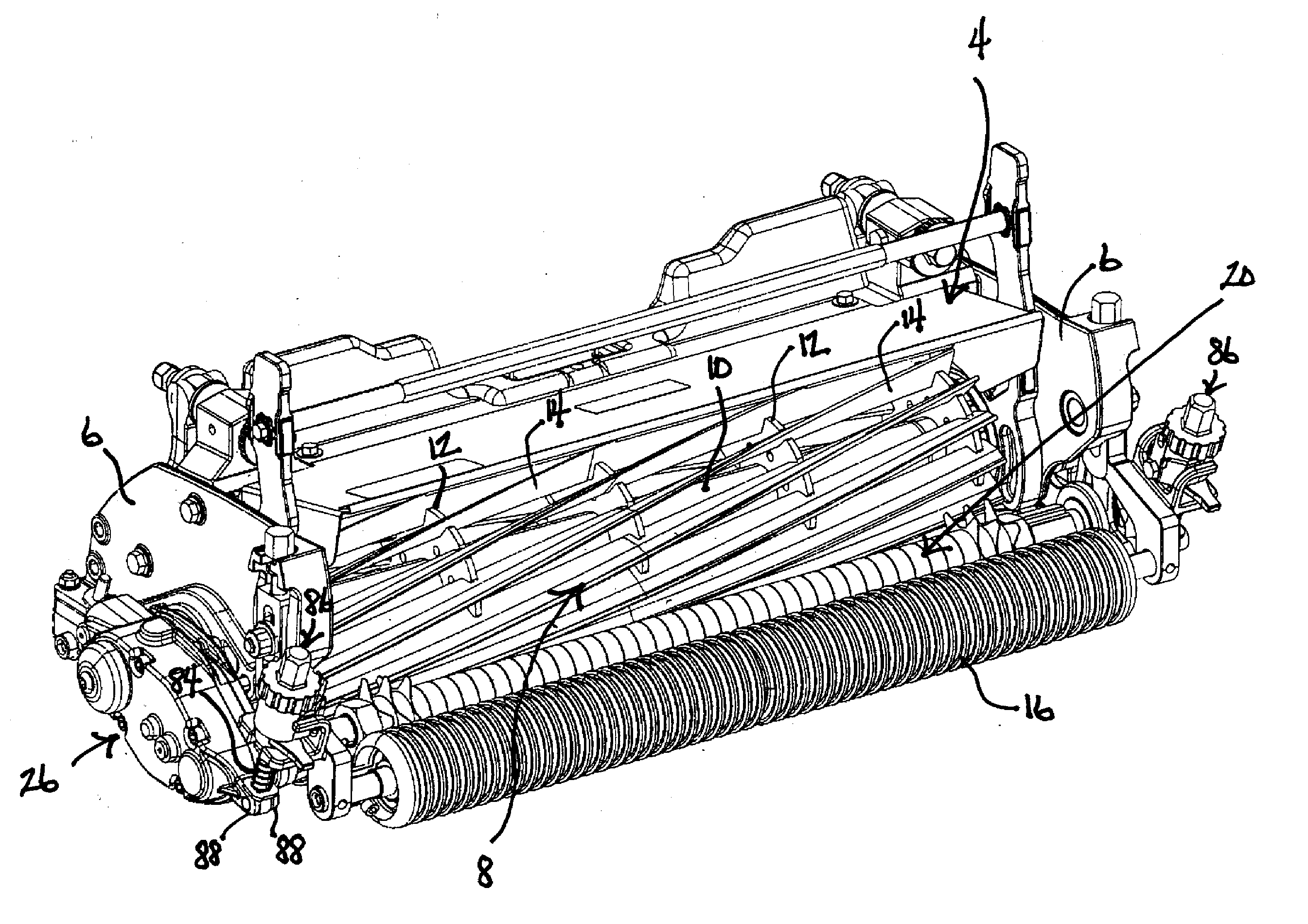
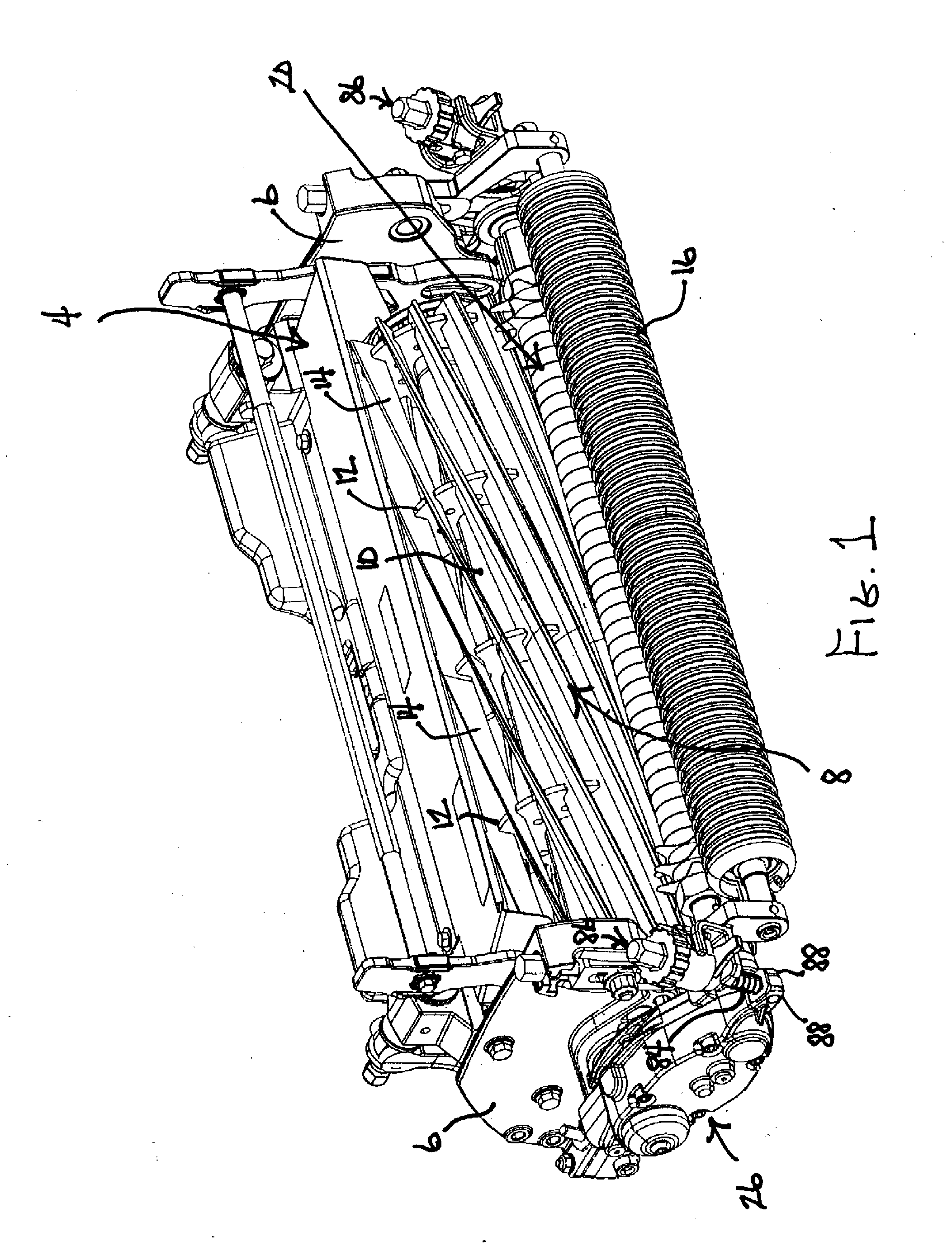
[0016]A reel cutting unit according to one embodiment of this invention is shown in FIG. 1 generally as 2. Cutting unit 2 comprises a frame 4 which includes laterally spaced side plates 6 that are rigidly joined to one another by various cross members. A rotatable cutting reel 8 is provided having a central reel shaft 10, a plurality of laterally spaced spiders 12 welded to reel shaft 10, and a plurality of laterally extending, helically twisted reel blades 14 welded to the peripheries of spiders 12 in a circumferentially spaced manner. Opposite ends of reel shaft 10 are rotatably journalled on side plates 6 to allow rotation of cutting reel 8 about a substantially horizontal rotational axis that is coaxial with the axis of reel shaft 10. As cutting reel 8 rotates, reel blades 14 of cutting reel 8 push stalks of grass against the sharpened cutting edge of a laterally extending bedknife (not shown) that is carried on frame 4 to cut the grass in a shearing action in a manner that is w...


PUM


Abstract

A turf groomer is coupled to a reel cutting unit in advance of the cutting reel and is powered by a gearbox having a rotary gear drive that is capable of selectively rotating the turf groomer in opposite directions at different speeds. The rotary gear drive is symmetrical about a plane through the axes of the input and output shafts thereof to permit the gearbox to be inverted to drive the turf groomer from either the left or right sides without requiring that two different models of the gear drive be available. The gearbox is connected to the reel cutting unit only by connecting the end of the input shaft to a shaft of the cutting reel and through a connection to a height adjuster for the turf groomer.

Description

TECHNICAL FIELD[0001]This invention relates to a reel mower having at least one reel cutting unit and a rotatable turf groomer for additionally acting on the turf surface during a mowing operation.BACKGROUND OF THE INVENTION[0002]Reel mowers having one or more reel cutting units are well known for cutting grass on a turf surface. Each reel cutting unit includes a rotatable cutting reel that pushes blades of uncut grass against a sharpened bedknife to cut the blades of grass using a shearing action between the reel blades and the bedknife. A rotatable turf groomer is also known for use on the cutting unit adjacent to the cutting reel for performing one or more additional actions on the turf surface during the mowing operation for promoting the healthy growth of the grass on the turf surface. These additional actions may comprise dethatching of the turf surface, cutting horizontal runners of grass, working a fertilizer or top dressing material into the turf surface, aerating the turf ...

Claims


Application Information

Patent Timeline
IPC IPC(8): A01D34/56A01D34/54A01D34/53
CPCA01D34/56A01D34/54A01D34/53A01D43/00
Inventor PATTON, ROBERT DAVIDSIREK, NICHOLAS JOHNGOMAN, GERALD EUGENE
Owner TORO CO THE
Why Eureka
Try Eureka