

Fluid coupling and method of manufacturing fluid coupling
- Summary
- Abstract
- Description
- Claims
- Application Information
AI Technical Summary
Benefits of technology
Problems solved by technology
Method used
Image

Examples
Embodiment Construction
[0037] Selected embodiments of the present invention will now be explained with reference to the drawings. It will be apparent to those skilled in the art from this disclosure that the following descriptions of the embodiments of the present invention are provided for illustration only and not for the purpose of limiting the invention as defined by the appended claims and their equivalents.
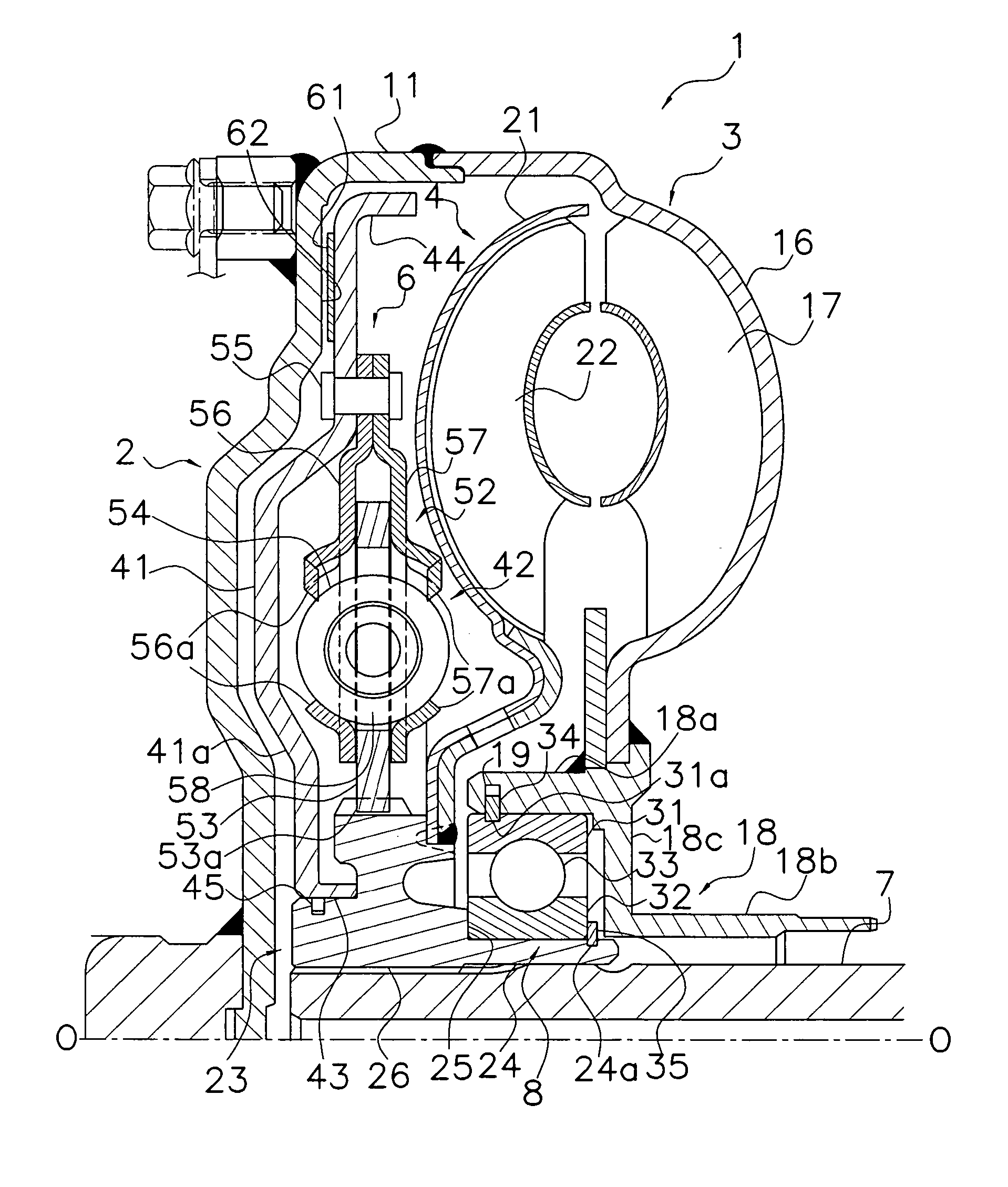
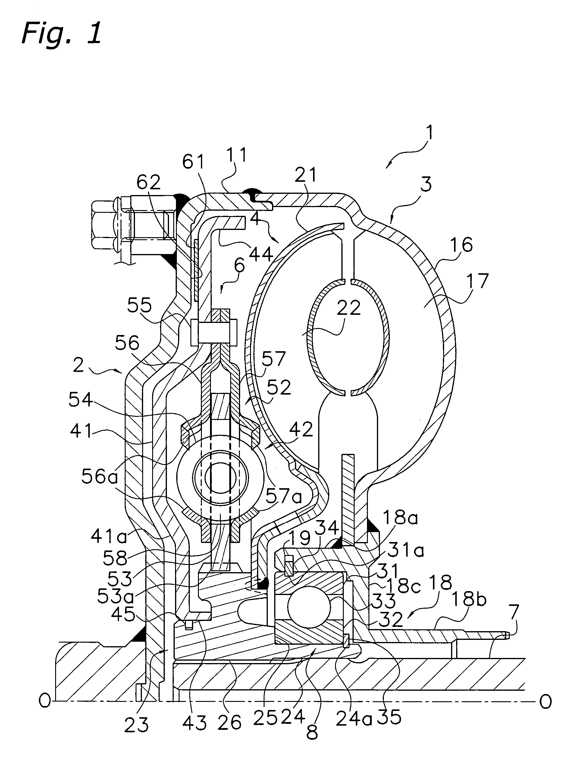
[0038]FIG. 1 is a cross-sectional view of a fluid coupling 1 in accordance with a preferred embodiment of the present invention. The fluid coupling 1 transmits torque from an engine (not shown) positioned at the left of FIG. 1 to a transmission (not shown) positioned at the right of FIG. 1. Line O-O in FIG. 1 represents the rotational axis of the fluid coupling 1.
Overall Configuration
[0039] The fluid coupling 1 is mainly configured by a front cover 2, an impeller 3, a turbine 4, and a lock-up clutch 6.
[0040] The front cover 2 is attachable to a constituent part of the unillustrated engine and...
PUM
| Property | Measurement | Unit |
|---|---|---|
| Diameter | aaaaa | aaaaa |
Abstract
Description
Claims
Application Information