

Method for determining vibratory contact stress at a blade attachment
- Summary
- Abstract
- Description
- Claims
- Application Information
AI Technical Summary
Benefits of technology
Problems solved by technology
Method used
Image

Examples
Embodiment Construction
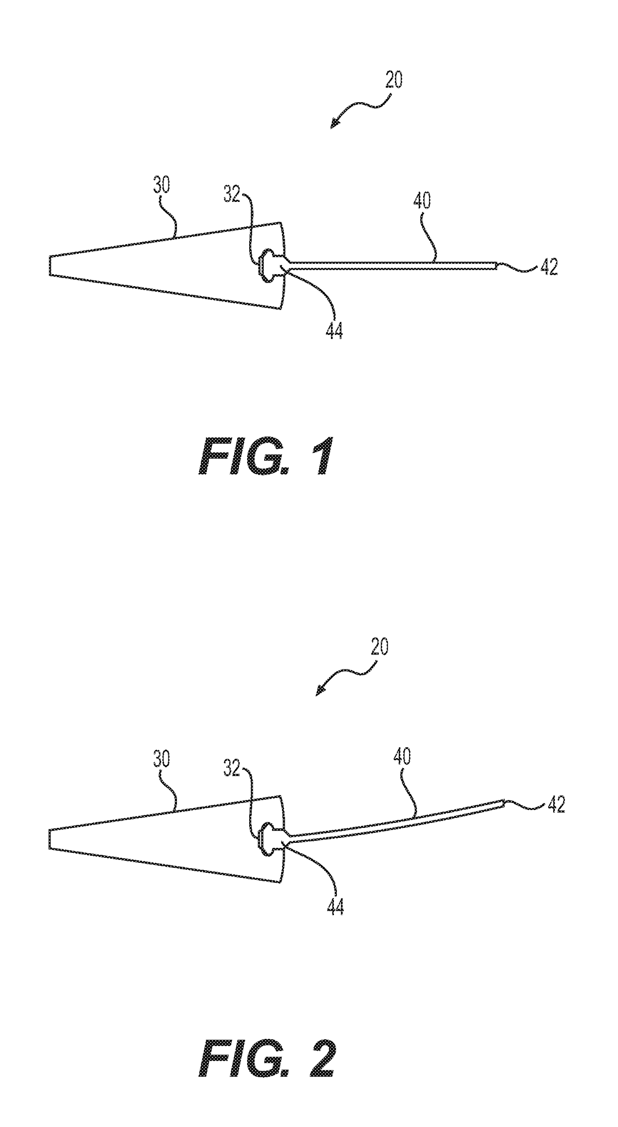
[0017]FIG. 1 illustrates a sector of a blade disk with a blade connected to the disk sector at a dove-tail type root connection. One of ordinary skill in the art will recognize that the dove-tail type root connection between the blade and the disk is illustrative of only one possible connection configuration. Alternative configurations of the connection between each blade and disk may include fir-tree type root connections and other root connections with different configurations and dimensions.
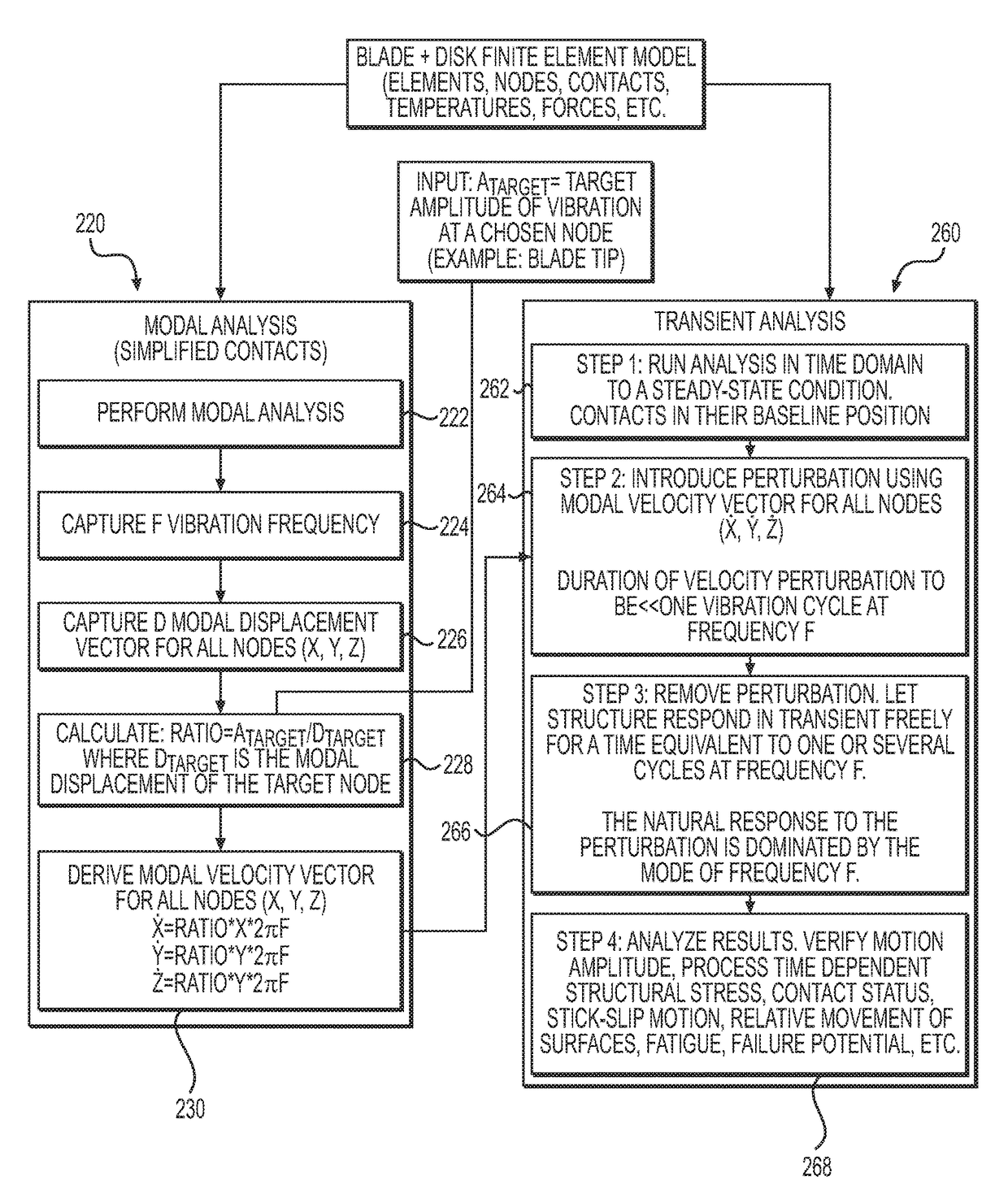
[0018]Blade vibration is generally recognized as one of the most significant causes of high cycle fatigue failure in gas turbine engines and other turbomachines. The blade root flexibility often cannot be determined easily in the assessment of blade vibration behavior, and exclusion of this effect may lead to a false prediction of vibration characteristics. Vibration characteristics of a blade and disk assembly may be determined through 3-D finite element analysis, together with laboratory or ...
PUM
 Abstract
Description
Claims
Application Information