
Swimming Pool Cleaner With Hydrocyclonic Particle Separator And/Or Six-Roller Drive System

Active Publication Date: 2016-07-28
HAYWARD IND INC
View PDF0 Cites 47 Cited by
  • Summary
  • Abstract
  • Description
  • Claims
  • Application Information

AI Technical Summary

Benefits of technology

The patent text describes a pool cleaner with a fine debris container and a central radial extension that separates small debris particles from large particles during the second cyclonic flow. A gasket is used between the large debris container and the central radial extension to maintain separation between the two groups of debris. The large debris container can be simultaneously emptied when the pool cleaner is in an open position. The technical effect of this design is that it improves the efficiency of the pool cleaner by separating debris particles of different sizes and facilitating their removal from the pool simultaneously.

Problems solved by technology

Swimming pools commonly require a significant amount of maintenance.
Additionally, leaves and other debris often times elude a pool filtration system and settle on the bottom of the pool, get stuck at the pool waterline, or float on the pool water surface.
The pool cleaner lengthens the life of the main pool filter (e.g., a sand, diatomaceous earth (D.E.), or cartridge filter) in fluid communication with the fluid circulation line of the swimming pool, and reduces the time between changes or backwash cycles of the main filter.
These traditional filter elements generally have limited surface area that can quickly become clogged or occluded by the debris and particulate that they are utilized to contain.
As the filter elements become clogged the cleaner can start to operate improperly, for example, the cleaner may lose suction performance.
That is, the surface of the bag, mesh, or basket can become clogged prior to the debris retention volume thereof being filled to capacity.
Further, to rinse or replace the filter elements, or empty the basket, a user will often have to directly handle the filter element and subsequently debris, and in the case of a basket, will have to open a lid of the cleaner to retrieve the basket from within the unit and spray the basket with water which may result in debris and water getting on them.
During cleaning, the pool cleaner will traverse the pool surfaces brushing or scrubbing the debris therefrom, often encountering obstacles, such as lights, drains, etc., along the way.
These obstacles can cause the cleaner to get stuck for the duration of a cleaning period, resulting in the pool being only partially cleaned.

Method used


Image

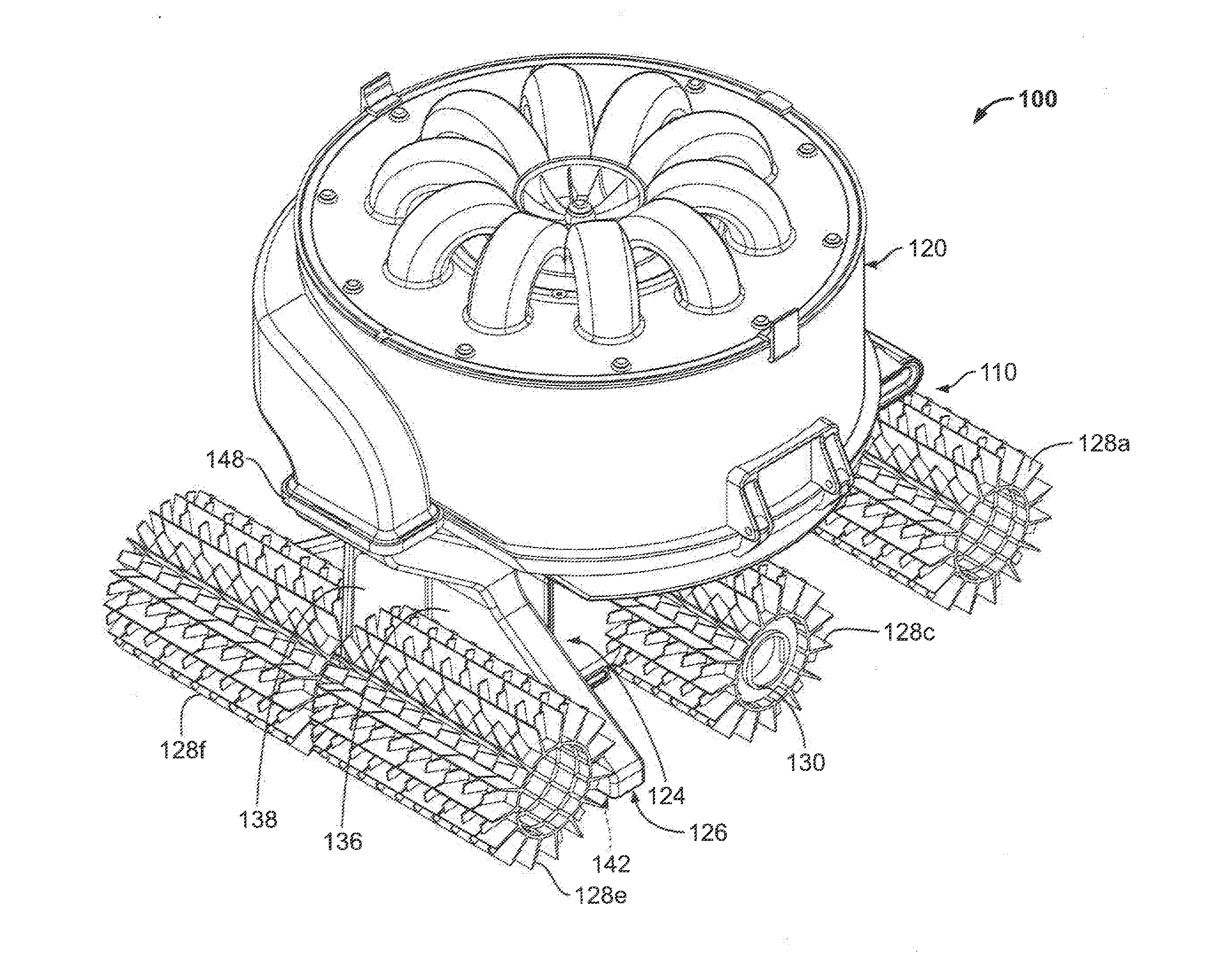
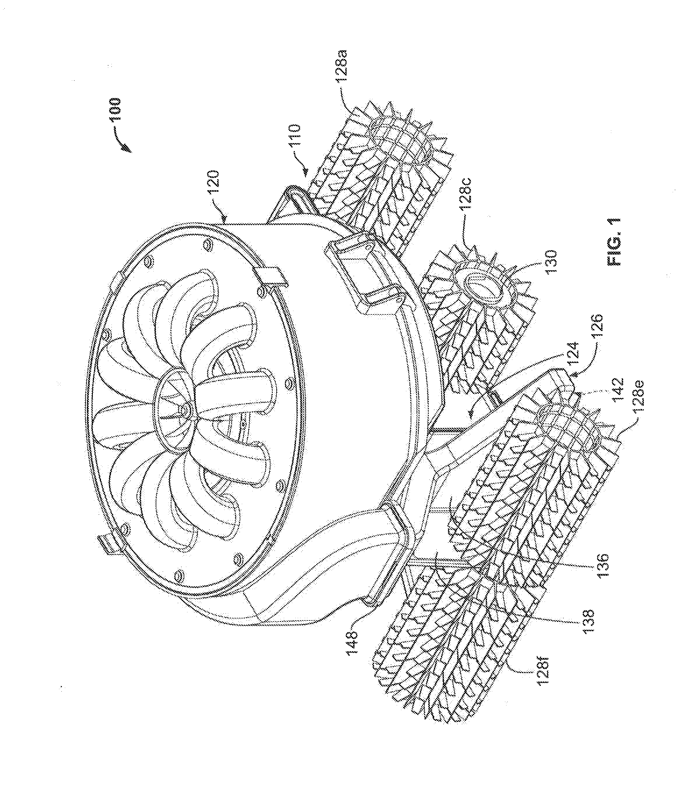
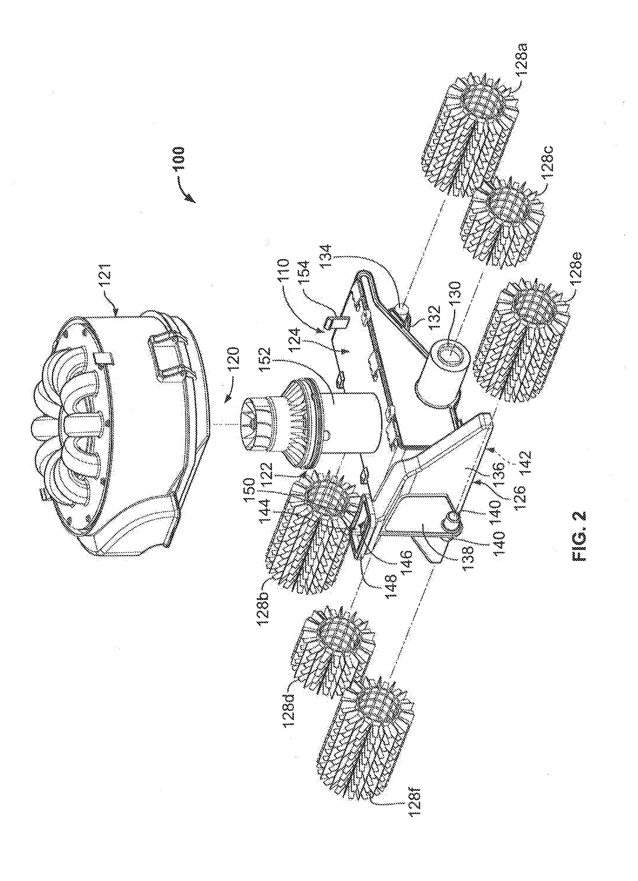
  • Swimming Pool Cleaner With Hydrocyclonic Particle Separator And/Or Six-Roller Drive System
  • Swimming Pool Cleaner With Hydrocyclonic Particle Separator And/Or Six-Roller Drive System
  • Swimming Pool Cleaner With Hydrocyclonic Particle Separator And/Or Six-Roller Drive System

Examples


second embodiment

[0116]With reference to FIGS. 20-28, perspective, top, side, exploded and sectional views of a hydrocyclonic particle separator assembly 400 are provided. It should be understood that the hydrocyclonic particle separator assembly 400 can be substantially similar in structure and function to the hydrocyclonic particle separator 120 and can be implemented with the pool cleaner 100 when suitable, as understood by one of ordinary skill in the art.

[0117]The hydrocyclonic particle separator assembly 400 includes a canister subassembly and a fluid turbine subassembly. In particular, the hydrocyclonic particle separator assembly 400 includes a diffuser 402 (e.g., a stator), a top cap 404, an impeller 406, an impeller skirt 408, an impeller retaining ring 466, a ring 410 of vortex finders 412, a vortex finder gasket 678, a shaft 414, and a ball bearing 416 disposed around the shaft 414. The hydrocyclonic particle separator assembly 400 further includes a cyclone block 418 with a plurality of...

third embodiment

[0151]With reference to FIG. 50, a bottom view of an exemplary pool cleaner 742 is provided. The pool cleaner 742 includes an outer housing or skin (not shown) in which one or more components of the pool cleaner 742 can be enclosed. The pool cleaner 742 can be substantially similar in structure and function to the pool cleaner 742, except for the distinctions noted herein. Therefore, like reference numbers are used for like structures. In particular, rather than including six rollers 710a-f, the pool cleaner 742 includes four brushed rollers 744a-d. Specifically, the pool cleaner 742 includes a single front roller 744a and a single rear roller 744d. The pool cleaner 742 includes a first roller drive 746 and a second roller drive 748 positioned on opposite sides of the motor housing 706. Each of the roller drives 746, 748 is in operative communication with respective first and second motors (not shown) positioned within the motor housing 706.

[0152]A first roller set (rollers 744a, 74...


PUM

PropertyMeasurementUnit
Perimeteraaaaaaaaaa

Abstract

Exemplary embodiments are directed to pool cleaners, generally including a canister body, a filtering medium assembly and a cyclone block. The canister body includes an inner chamber within inner walls of the canister body. The filtering medium assembly can be disposed within the inner chamber of the canister body. The cyclone block can be disposed within the inner chamber of the canister body and can be at least partially surrounded by the filtering medium assembly. The cyclone block includes a plurality of individual cyclone containers. A first cyclonic flow can be generated between the inner walls of the canister body and the filtering medium assembly. A second cyclonic flow can be generated within each of the plurality of cyclone containers.

Description

CROSS-REFERENCE TO RELATED APPLICATIONS[0001]This application claims the benefit of U.S. Patent Application No. 62 / 107,565, filed on Jan. 26, 2015. The entire content of the foregoing provisional patent application is incorporated herein by reference.FIELD OF THE PRESENT DISCLOSURE[0002]Embodiments of the present disclosure relate to swimming pool cleaners and, more particularly, to automatic swimming pool cleaners movable along all pool surfaces including a pool waterline or water surface for purposes of cleaning debris therefrom, associated apparatus for separating debris from a fluid stream traveling through the swimming pool cleaner, and apparatus for facilitating maintenance of a swimming pool cleaner and associated apparatus.BACKGROUND OF THE PRESENT DISCLOSURE[0003]Swimming pools commonly require a significant amount of maintenance. Beyond the treatment and filtration of pool water, the bottom wall (the “floor”) and side walls of a pool (the floor and the side walls collectiv...

Claims


Application Information

Patent Timeline
IPC IPC(8): E04H4/16B04C9/00C02F1/00B01D21/26C02F1/38
CPCE04H4/1654B01D21/267C02F1/385B04C2009/002B04C9/00C02F2103/42C02F2201/008C02F1/001B04C5/26B04C5/28B04C5/24
Inventor HAYES, GRAHAM M.TEUSCHER, SCOTTMARCIANO, EDWARD LAWRENCE
Owner HAYWARD IND INC
Learn More