Rotating assembly comprising a transmission member and an oil distribution system

a technology of oil distribution system and transmission member, which is applied in the direction of gear lubrication/cooling, toothed gearings, gearings, etc., can solve the problems of fuel cost, operating cost constraints, and certain difficulties that need to be overcom

Active Publication Date: 2016-07-28
SN DETUDE & DE CONSTR DE MOTEURS DAVIATION S N E C M A
View PDF8 Cites 8 Cited by
  • Summary
  • Abstract
  • Description
  • Claims
  • Application Information

AI Technical Summary

Benefits of technology

[0051]In other embodiments, leaks of oil at the interface between the oil distribution system and the casing maintain a film of oil. The sealing segments are dimensioned in such a manner as to ensure that the pressure of the oil enables the oil to go beyond the sealing segments in order to initiate the oil film. The oil film serves to lubricate the interface between the oil distribution system and the casing so as to ensure it rotates properly. The casing surrounding the distribution system and the transmission member preferably forms a closed enclosure enabling the oil to be recovered and preventing it from polluting or being polluted by other elements of the turbine engine.

Problems solved by technology

Nevertheless, because of ever-increasing constraints on operating costs, closely associated with the cost of fuel, which nowadays is very high, new turbojet projects have been proposed that benefit from lower specific consumption.
A turbojet with a gearbox thus presents important qualities, but at present certain difficulties still remain that need to be overcome before launching industrial production.
In a conventional gearbox, these functions are traditionally provided by a flow of oil fed centrifugally; nevertheless, it has been found that the pressure of the oil is not sufficient in such configurations of gearbox turbojets to ensure that centrifugal feeding is effective.
Nevertheless, that solution is not satisfactory either since the operation of the oil transfer bearing is greatly disturbed by the erratic movements and changes in axis of the gearbox caused by the large amount of vibration to which it is subjected: in particular, it is found that the oil transfer bearing is the seat of premature wear thereby affecting the feed of oil and thus the lifetime of the gearbox.

Method used


Image

  • Rotating assembly comprising a transmission member and an oil distribution system
  • Rotating assembly comprising a transmission member and an oil distribution system
  • Rotating assembly comprising a transmission member and an oil distribution system

Examples


Embodiment Construction

[0062]In order to make the invention more concrete, examples of rotary assemblies are described in detail below with reference to the accompanying drawings. It should be recalled that the invention is not limited to these embodiments.

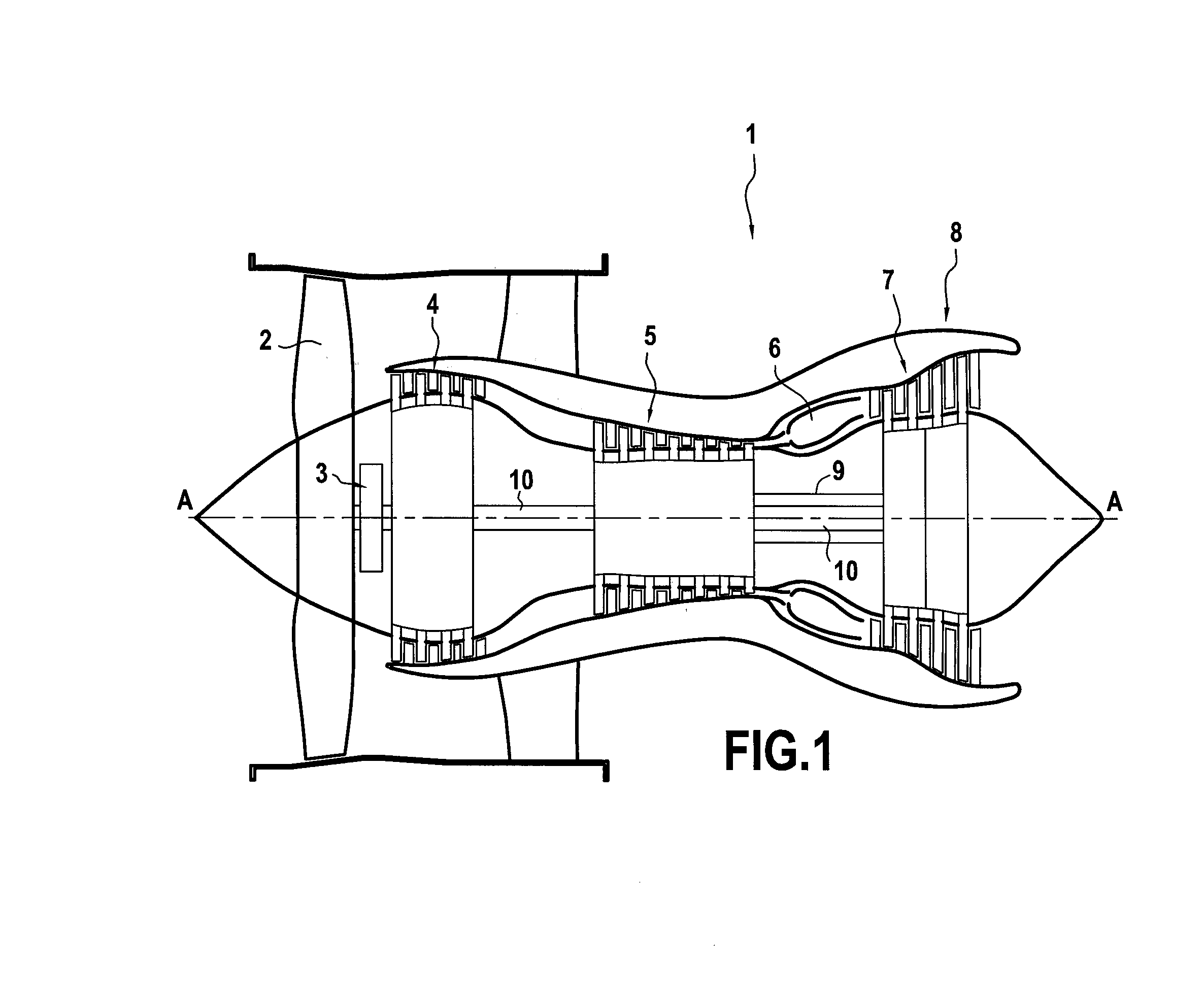
[0063]FIG. 1 is a section view of a bypass turbojet 1 with a gearbox of the invention shown in a vertical plane containing its main axis A. Going from upstream to downstream, the jet comprises a fan 2, a gearbox 3, a low pressure compressor 4, a high pressure compressor 5, a combustion chamber 6, a high pressure turbine 7, and a low pressure turbine 8.

[0064]In such a turbojet 1 with a gearbox, the high pressure turbine 7 drives the high pressure compressor 5 via a high pressure shaft 9. The low pressure turbine 8, also referred to as a fast turbine, drives the low pressure compressor 4, also referred to as a fast compressor, via low pressure shaft 10. The fast turbine 8 also drives the fan 2 via the speed-reduction gearbox 3. In this way, the fan 2 may ...


PUM


Abstract

A rotary assembly comprising a transmission member and an oil distribution system enabling oil to be supplied to the transmission member in order to lubricate it. According to the invention, the oil distribution system comprises at least one oil transfer chamber provided with at least one feed orifice configured to receive oil from outside the rotary assembly; the transmission member includes at least one rotary portion provided with at least one oil reception chamber; at least one link duct provides fluid flow connection between the oil transfer chamber and the oil reception chamber; the oil distribution system is driven by said rotary portion of the transmission member to rotate together with it; and the rotary assembly is configured in such a manner as to accommodate a given amount of axial and/or radial relative movement between said rotary portion of the transmission member and the oil distribution system.

Description

FIELD OF THE INVENTION[0001]The present description relates to a rotary assembly comprising a transmission member and an oil distribution system serving to supply oil to the transmission member in order to lubricate it.[0002]Such a rotary assembly may be used in particular in the field of aviation, within airplane turbojets or within helicopter turboshaft engines, to mention only these examples.STATE OF THE PRIOR ART[0003]The turbojets that are conventionally to be found these days in the field of civil aviation are bypass turbojets with two spools. Nevertheless, because of ever-increasing constraints on operating costs, closely associated with the cost of fuel, which nowadays is very high, new turbojet projects have been proposed that benefit from lower specific consumption.[0004]One promising option consists in fitting a turbojet with a speed-reducing gearbox interposed between the low pressure compressor and the fan: in this way, it is possible to increase the speed of rotation o...

Claims


Application Information

Patent Timeline
Patent Type & Authority Applications(United States)
IPC IPC(8): F16H57/04
CPCF16H57/042F16H57/0479F02C7/36F16H1/2827F16H57/0482
Inventor BRAULT, MICHEL GILBERT ROLANDLEMARCHAND, KEVIN
Owner SN DETUDE & DE CONSTR DE MOTEURS DAVIATION S N E C M A
Why Eureka
Try Eureka