Device for controlling the distribution of fluid ejected from a fluid nebulizing dispenser

a technology of fluid ejection and control device, which is applied in the direction of optical radiation measurement, structural/machine measurement, instruments, etc., can solve the problem that the check does not allow the testing of all manufactured dispensers, and achieve the effect of preventing the contamination of the dispenser itsel

Inactive Publication Date: 2016-07-28
INMAN
View PDF7 Cites 9 Cited by
  • Summary
  • Abstract
  • Description
  • Claims
  • Application Information

AI Technical Summary

Benefits of technology

[0008]It is an object of the present invention to provide a system for recognizing the proper shape of the dispensing cone of a nebulizing, or spraying, dispenser, or the like. In particular, it is an object of the present invention to provide a system able to perform a non-invasive check thereby preventing the contamination of the dispenser itself, such that the latter can be put on the market.
[0017]In other words, the temperature difference between the fluid and the surrounding space allows the detecting means to identify the presence of the fluid nebulized by the dispenser downstream of the discharging nozzle.
[0019]The thermographic sensors, typically thermographic cameras, make the capture of an image of the nebulized fluid possible.
[0022]This allows to minimize the waiting times between the check of two different dispensers. This waiting time depends on the time taken to lead the contact surface to a uniform temperature in response to a check, that is the time taken to erase the mark of the fluid nebulized by a dispenser.

Problems solved by technology

Clearly, this is a time-consuming check which requires labor and causes the waste of the randomly chosen containers, thereby preventing them from being put on the market.
Moreover, this kind of check does not allow to test all the manufactured dispensers.

Method used


Image

  • Device for controlling the distribution of fluid ejected from a fluid nebulizing dispenser
  • Device for controlling the distribution of fluid ejected from a fluid nebulizing dispenser
  • Device for controlling the distribution of fluid ejected from a fluid nebulizing dispenser

Examples


second embodiment

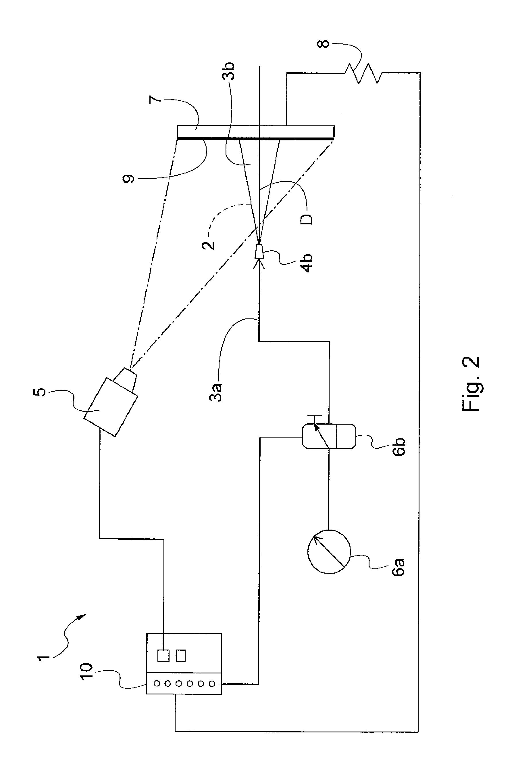
[0045]In a second embodiment, the distribution 2 of the fluid 3b is indirectly detected.

[0046]In particular, referring to the embodiments of FIGS. 2 and 3, the contrast space 7 comprises a contact surface 7. Special means 8 heat the surface 7 up to a temperature different from the temperature of the fluid 3a, 3b. Alternatively, means can be provided which lead the temperature of the surface 7 so as to be lower than the temperature of the fluid 3a, 3b.

[0047]According to further variations, the means 8 operate on the fluid 3a, 3b by cooling or heating it with respect to the contact surface 7.

[0048]Preferably, the contact surface 7 is covered by a film 9 made of a thermal-insulating material, for example Teflon. As better explain hereinafter, the film 9 allows to minimize the time between two subsequent checks of two different dispensers 4.

[0049]The surface 7 is arranged so as to be incident to the fluid 3b ejected from the dispenser 4. Preferably, the contact surface 7 is arranged so...

first embodiment

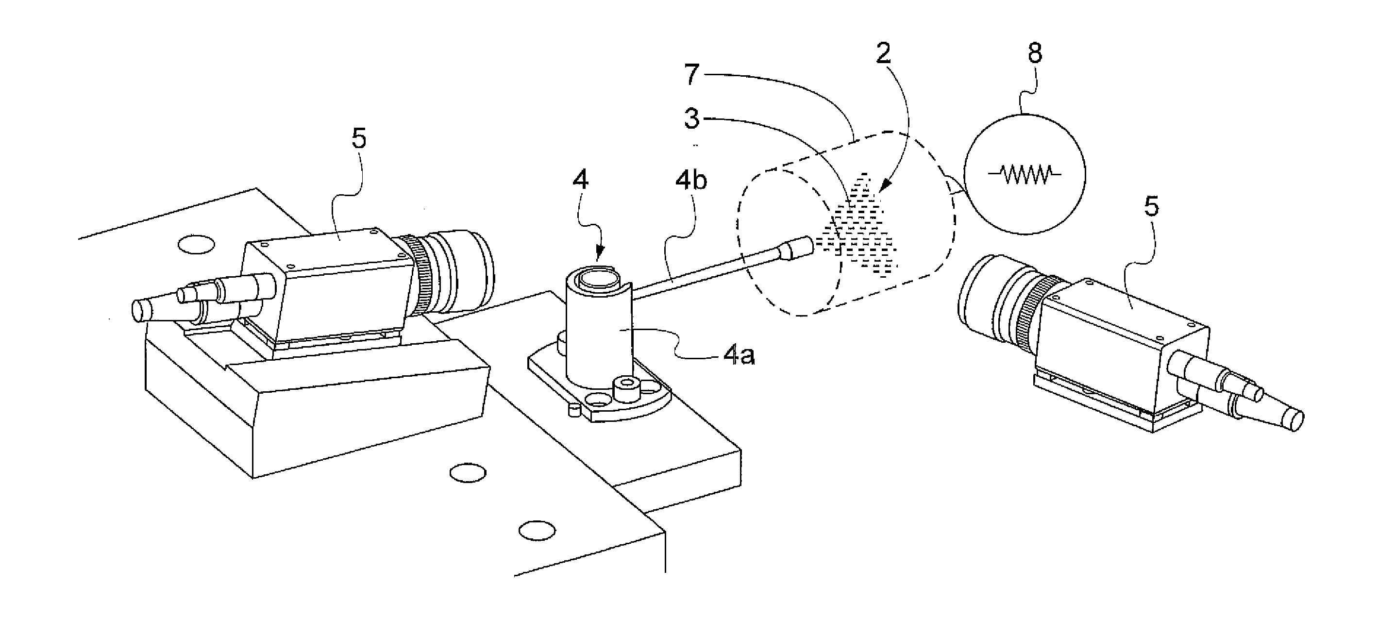
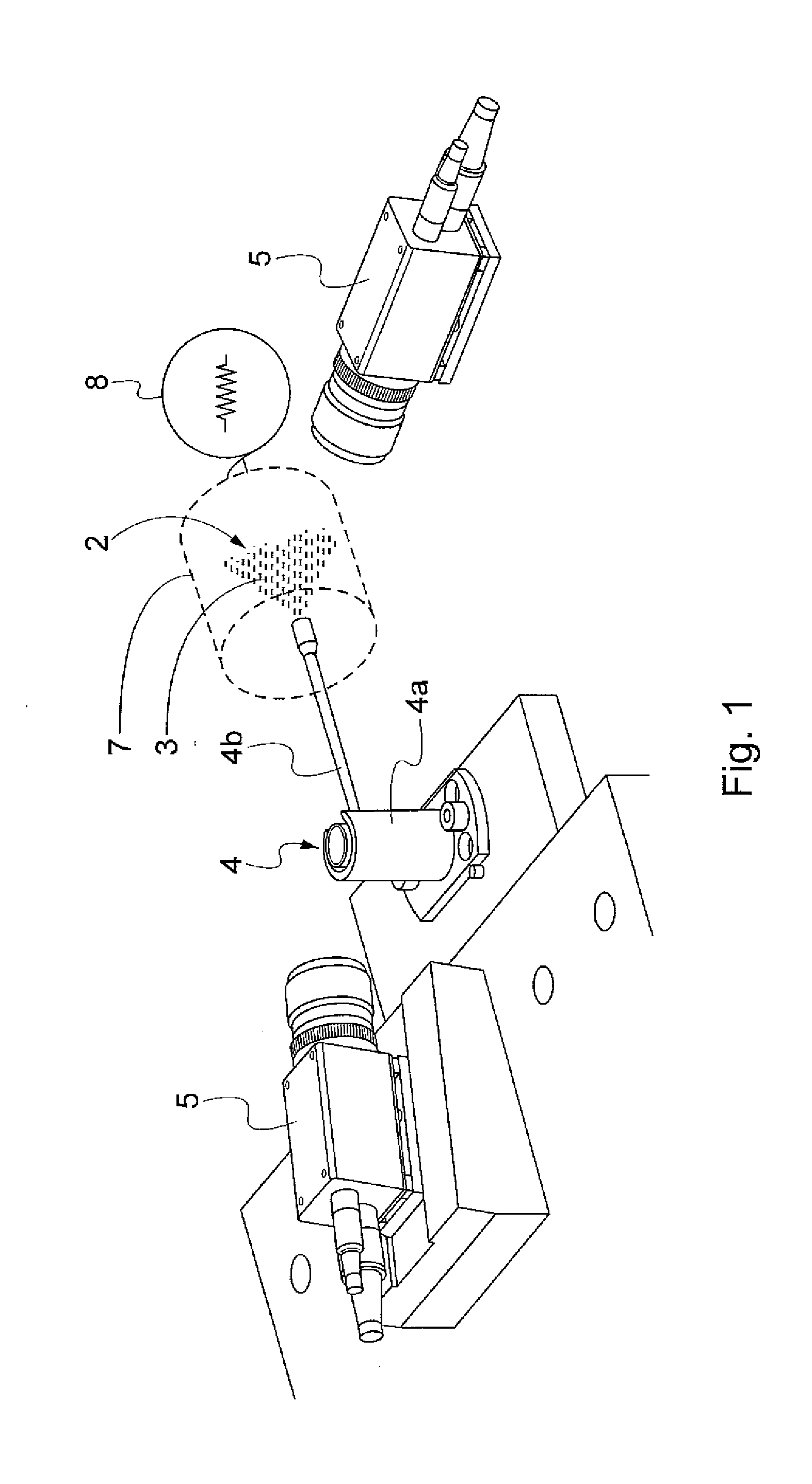
[0060]In the previously described first embodiment, the means 5 directly identify (e.g. by a thermographic picture) the distribution of fluid 3b, i.e. the “cone” formed by the fluid 3b downstream of the dispenser 4.

[0061]In the second embodiment, the means 5 indirectly identify the distribution of fluid 3b, in particular by detecting a section or mark 7b (stamped on the surface 7 or on the film 9) of the “cone” formed by the fluid 3b downstream of the dispenser 4. Preferably, the means 5 are able to identify the shape of the mark 7a, the size of the mark 7a, the position of the center of the mark 7a.

[0062]Having these three data and preferably knowing the position of the discharging nozzle 4b as well, it is possible to define the proper geometry of the distribution 2 of the nebulized fluid 3b and check if the shape, size and direction of the distribution 2 are correct.

[0063]As previously mentioned, preferably the surface 7 may be covered by a thermal-insulating film 9, for example ...


PUM


Abstract

Disclosed is a device for checking the distribution of fluid ejected from a nebulizing dispenser of fluid, of the type including a discharging nozzle for a nebulized fluid. The device having detecting means for detecting the temperature difference between at least part of the nebulized fluid ejected from the dispenser and a one contrast space, and / or the temperature difference caused by the nebulized fluid ejected from the dispenser to the contrast space. In this case, the contrast space is arranged so as to be at least partially incident to said nebulized fluid.

Description

CROSS-REFERENCE TO RELATED APPLICATIONS[0001]This Application claims the benefit of European Patent Application No. EP15152564.9 filed Jan. 26, 2015, the contents of which are incorporated herein by reference.FIELD OF THE INVENTION[0002]The present invention relates to the check of fluid nebulizing dispensers (or actuators) mainly dedicated to pharmaceutical, medical or cosmetic sectors.BACKGROUND OF THE INVENTION[0003]The dispensing quality of a pharmaceutical or cosmetic product dispensed from these devices is a key requirement of the market.[0004]Not only do the proper nebulization and the correct amount of dispensed product determine this quality, but also the dispensing shape / dimension / direction of this product that should preferably take the shape of a cone downstream of the dispenser.[0005]The known art provides a manual sampled check of some dispensing devices by inserting a colored liquid for simulating the product inside the dispenser and dispensing such liquid against a d...

Claims


Application Information

Patent Timeline
Patent Type & Authority Applications(United States)
IPC IPC(8): G01B21/20B05B1/02B05B12/00G01J5/00
CPCG01B21/20G01J5/0037G01J2005/0077B05B12/004B05B1/02B05B12/082B05B12/084A61M11/00A61M2209/02G01M1/00
Inventor BETTINELLI, VINCENZO
Owner INMAN
Why Eureka
Try Eureka