Photosensitive member unit and image forming apparatus including the same

a technology of image forming apparatus and photosensitive member, which is applied in the direction of electrographic process, wing accessories, instruments, etc., can solve the problems of charging roller contacting the photosensitive member unintentionally, deformation of the proportion of the charging roller contacting the photosensitive member, and burden on the user of removing the spaces

Active Publication Date: 2016-07-28
CANON KK
View PDF2 Cites 12 Cited by
  • Summary
  • Abstract
  • Description
  • Claims
  • Application Information

AI Technical Summary

Benefits of technology

[0010]Accordingly, it is an object of the present invention to provide a photosensitive member unit and an image forming apparatus comprising t

Problems solved by technology

In such a contact charging type, if the photosensitive member unit is left unoperated for a long term with the charging roller being in contact with the photosensitive member, the portion of the charging roller contacted with the photosensitive member is deformed with the result of image defect when the photosensitive member unit is operated after the long-term unoperated state.
With such a structure, however, a burden of removing the spaces is placed on the user when the photosensitive member unit is mounted to the main assembly of the image forming apparatus.
However, with the structure disclosed in Japanese Laid-open Patent Application Hei 11-95532, there is a likelihood that the photosensitive member rotates by a vibration imparted to the photosensitive member unit in the period from the shipment of the photosensitive member unit to the mo

Method used


Image

  • Photosensitive member unit and image forming apparatus including the same
  • Photosensitive member unit and image forming apparatus including the same
  • Photosensitive member unit and image forming apparatus including the same

Examples


embodiment 1

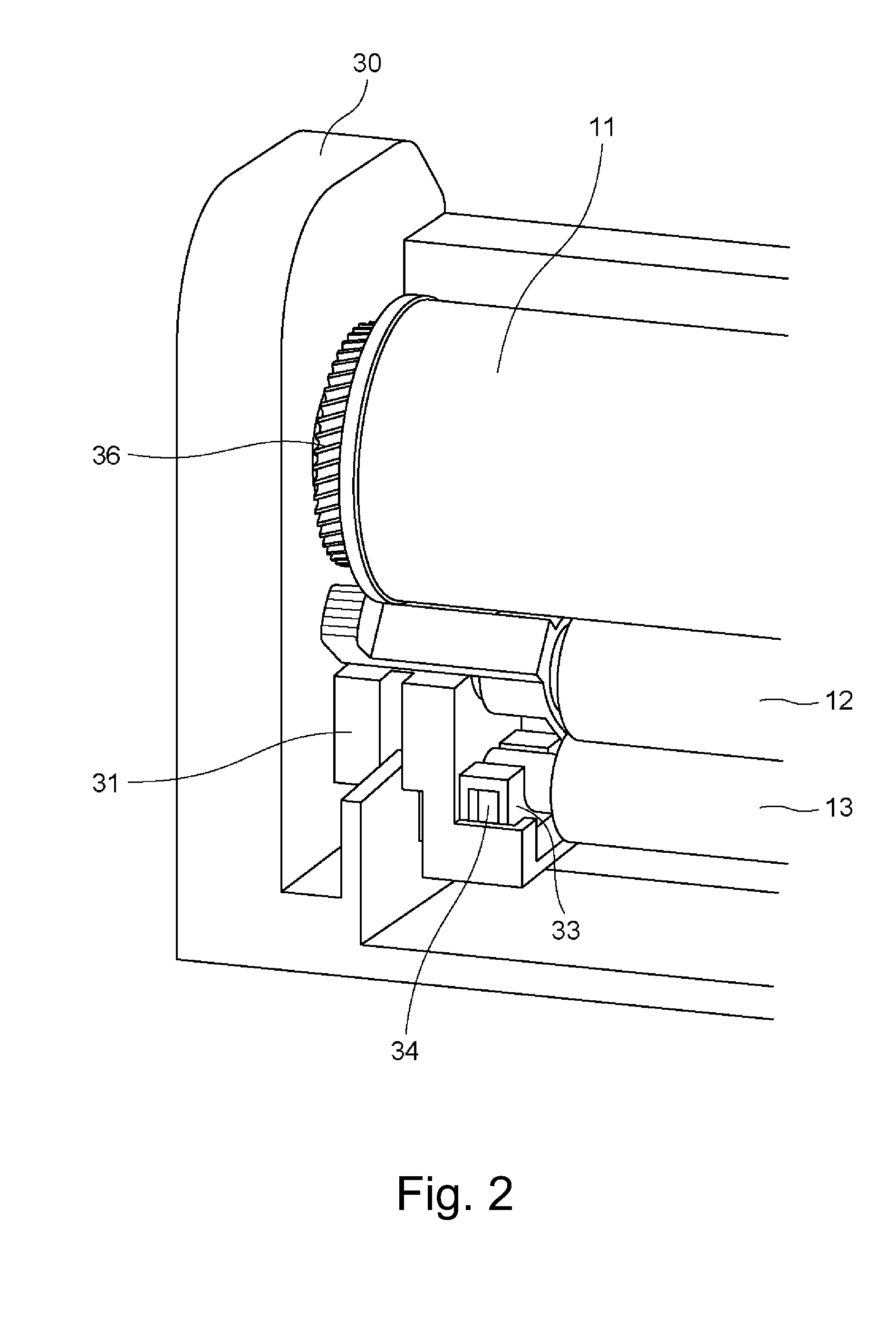
[0033]Referring first to FIG. 1, a general arrangement and operation of an image forming apparatus will be described. Then, the description will be made as to a space keeping mechanism for keeping the spacing between the photosensitive member and a charging roller as a charging member, and an automatic releasing mechanism for the space keeping mechanism operable with the driving of the photosensitive member supplied with a driving force from the main assembly of the image forming apparatus.

(General Arrangement and Operation of Image Forming Apparatus)

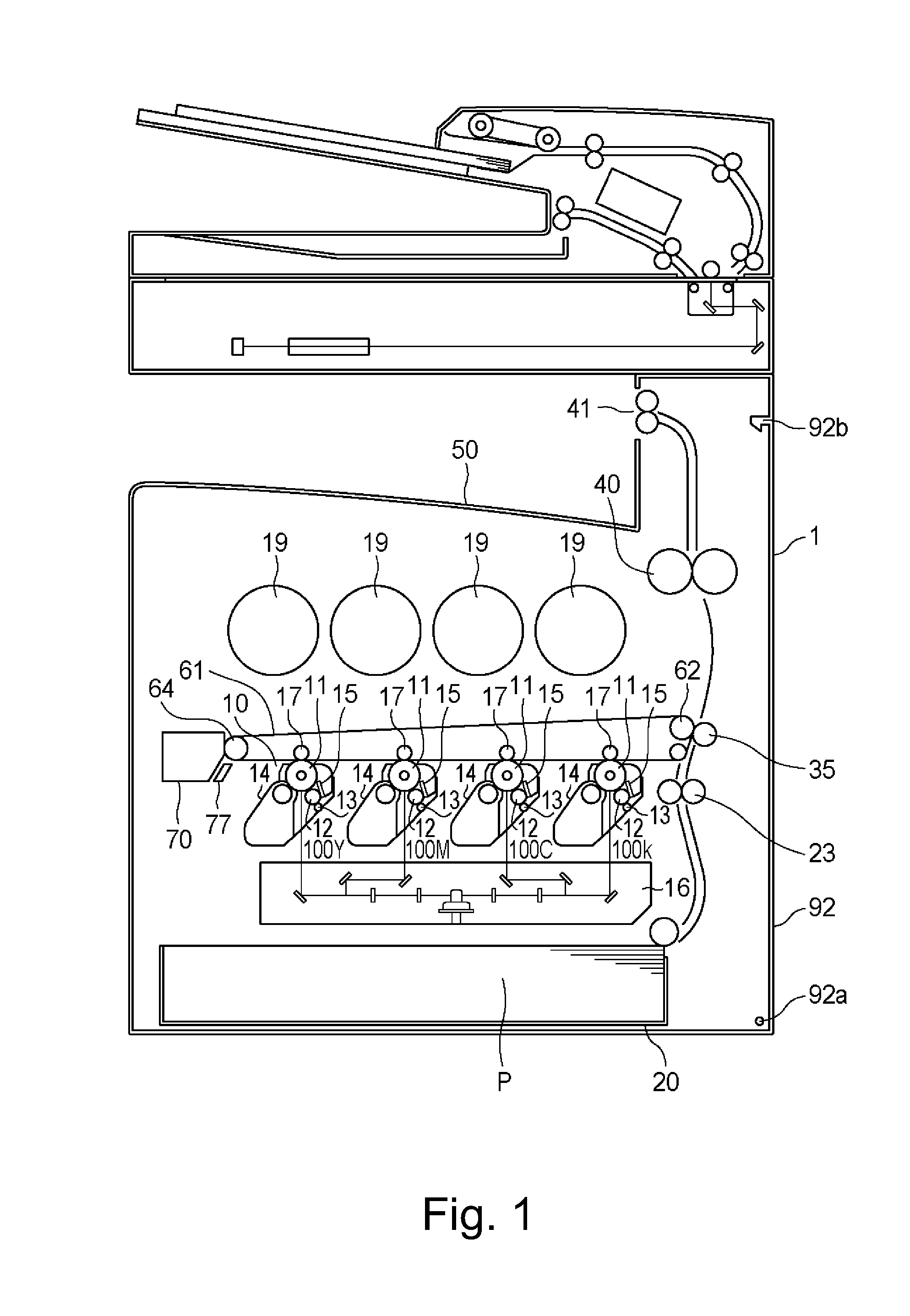
[0034]FIG. 1 is a schematic sectional view of the image forming apparatus according to an embodiment of the present invention. The image forming apparatus 1 of this embodiment is an intermediary transfer type and tandem type image forming apparatus which is capable of forming a full-color image using an electrophotographic type.

[0035]The image forming apparatus 1 of this embodiment comprises image forming stations for forming toner imag...

embodiment 2

[0092]In Embodiment 1, the engaging portion 211 is in the form of gear teeth, but this is not inevitable to the present invention, and the engaging portion 211 may be any if it can engage with the gear 36 to receive the rotational force from the gear 36, and as shown in FIG. 10, it may comprise projections disposed in the same pitch as the gear teeth pitch of the 36 without deteriorating the advantageous effects of Embodiment 1.

(Engaging Portion in Embodiment 2)

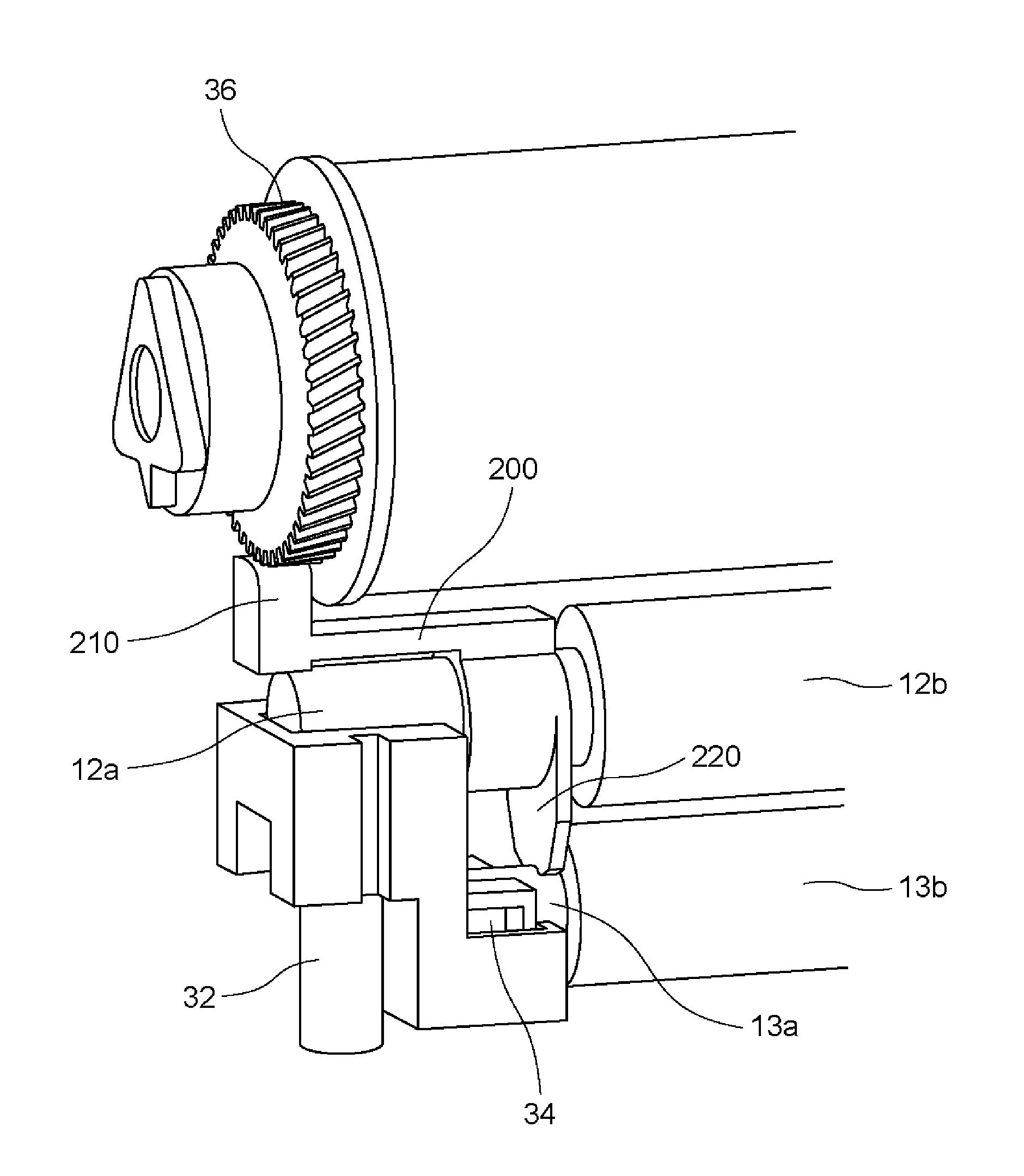
[0093]FIG. 11 illustrates the engaging portion between the engaging portion 211 of the space keeping member 200 and the photosensitive member gear 36. FIG. 12 is a perspective view of the photosensitive member gear 3 and the structure therearound in this embodiment.

[0094]As shown in FIG. 12, in this embodiment, the gear 37 is engaged with the photosensitive member gear 36, and the driving force of the photosensitive member gear 36 is transmitted through the gear 37 to drive the toner feeding screw.

[0095]As shown in FIG. 11, i...

embodiment 3

[0107]In Embodiments 1, 2, the projected portion 211a is provided on the space keeping member 200, but in Embodiment 3 which will be described in the following, the projected portion 211a is not provided.

[0108]FIG. 14 is an illustration of a contact portion between the space keeping member 200 and the photosensitive member gear 36 in this embodiment.

[0109]As shown in FIG. 14, the surface of the space keeping member 200 opposed to the photosensitive member gear 36 is provided with a surface 213 which is contacted by the free end of the gear tooth 36a of the photosensitive member gear 36 in the spaced state in which the photosensitive drum 11 and the charging roller 12 are spaced from each other. The contact surface 213 is a smooth surface made of material having a relatively high friction coefficient such as rubber or the like.

[0110]When the spaced state is to be disestablished, the space keeping member 200 is rotated by the frictional force between the free end of the gear tooth 36a...


PUM


Abstract

A photosensitive member unit for an image forming apparatus includes a rotatable photosensitive drum; a charging roller including an elastic layer; a first spring urging the roller toward the drum; a drive receiving portion provided on the drum; a rotatable spacer including a contact portion contacted to the drive receiving portion and capable of receiving the driving force through the drive receiving portion, the spacer being rotatable between a spacing position for maintaining a spaced state in which the contact portion contacts the drive receiving portion to space the roller from the drum, and a contact position in which the spaced state between the drum and the roller is disestablished, and the spacer being movable toward the drum; a supporting member urging the spacer in a state that spacer is in the spacing position; and a second spring urging the supporting member toward a rotation axis of the spacer.

Description

FIELD OF THE INVENTION AND RELATED ART[0001]The present invention relates to a photosensitive member unit mountable to an image forming apparatus using an electrophotographic process and an image forming apparatus comprising the same.[0002]For the purpose of making maintenance operation easy, an image forming apparatus of an electrophotographic type with which the photosensitive member unit including a photosensitive member and parts for the image formation as a unit is exchangeable is known. In the image forming apparatus of such a type, a contact charging type charging roller (charging member) having an elastic layer for charging the photosensitive member in contact with the photosensitive member using an urging force provided by a spring or the like is widely used.[0003]In such a contact charging type, if the photosensitive member unit is left unoperated for a long term with the charging roller being in contact with the photosensitive member, the portion of the charging roller co...

Claims


Application Information

Patent Timeline
IPC IPC(8): G03G21/18
CPCG03G21/1814G03G21/1828G03G15/0216G03G21/1821B66B13/06B66B13/24B66B13/306E05Y2800/41E05Y2900/104E06B3/46E06B7/36G03G21/181
Inventor KATAYAMA, HIROMASA
Owner CANON KK
Why Eureka
Try Eureka