
Method and apparatus for determining disparity

a technology of disparity and depth, applied in the field of determining disparities or depths, can solve the problems of limited resolution of depth information acquired based on a disparity corresponding to a unit of pixel size, high complexity of above-determining calculations,

Active Publication Date: 2016-07-28
SAMSUNG ELECTRONICS CO LTD
View PDF1 Cites 3 Cited by
  • Summary
  • Abstract
  • Description
  • Claims
  • Application Information

AI Technical Summary

Benefits of technology

The patent describes a method and apparatus for determining the movement direction and disparity between sensors. This can be useful in various applications such as autonomous vehicles and robotics. The method involves receiving signals from sensors at different locations and extracting the movement direction based on those signals. The apparatus includes an extractor and a processor to determine the movement direction and disparity. The technical effects of this patent include improved accuracy in determining movement direction and disparity, which can aid in the development of more advanced systems such as autonomous vehicles.

Problems solved by technology

However, the above determining has a high complexity of calculation.
In addition, a resolution of depth information acquired based on a disparity corresponding to a unit of a pixel size is limited.
Also, the exemplary embodiments are not required to overcome the disadvantages described above, and may not overcome any of the problems described above.

Method used


Image

  • Method and apparatus for determining disparity
  • Method and apparatus for determining disparity
  • Method and apparatus for determining disparity

Examples


Embodiment Construction

[0055]Exemplary embodiments are described in greater detail herein with reference to the accompanying drawings.

[0056]In the following description, like drawing reference numerals are used for like elements, even in different drawings. The matters defined in the description, such as detailed construction and elements, are provided to assist in a comprehensive understanding of the exemplary embodiments. However, it is apparent that the exemplary embodiments can be practiced without those specifically defined matters. Also, well-known functions or constructions are not described in detail since they would obscure the description with unnecessary detail.

[0057]In addition, the terms such as “unit”, “-er (-or)”, and “module” described in the specification refer to an element for performing at least one function or operation, and may be implemented in hardware, software, or the combination of hardware and software.

[0058]Exemplary embodiments to be described below may be used to measure a d...


PUM


Abstract

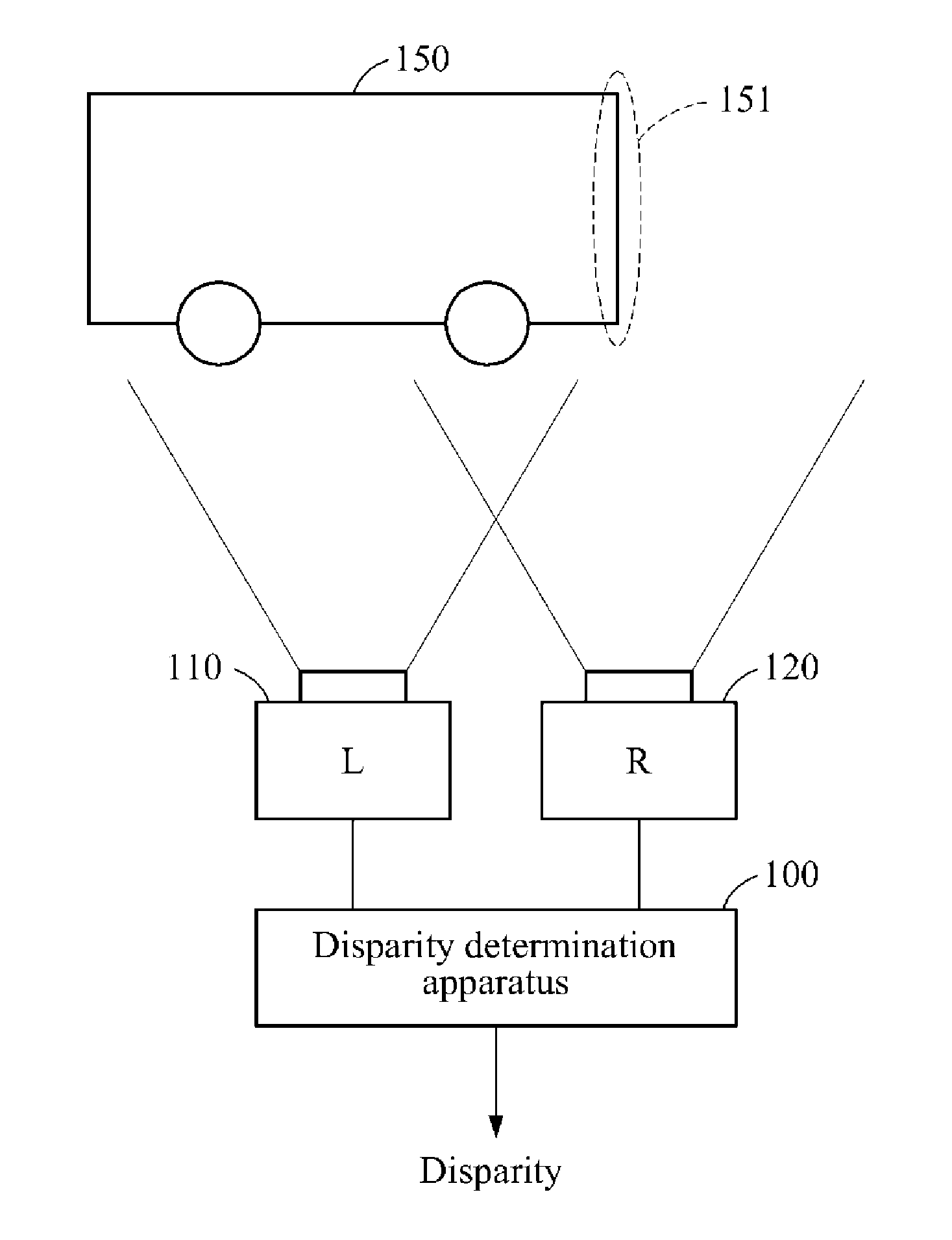
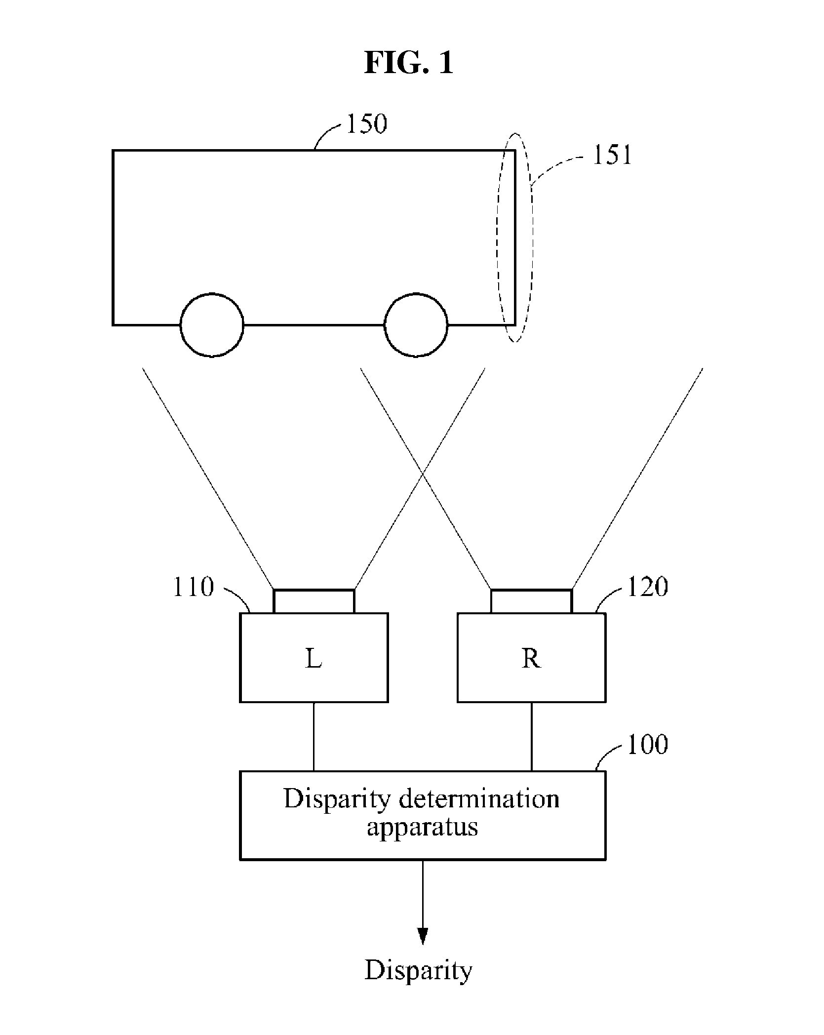
A disparity determination method and apparatus are provided. The disparity determination method includes receiving first signals of an event from a first sensor disposed at a first location and second signals of the event from a second sensor disposed at a second location that is different than the first location, and extracting a movement direction of the event, based on at least one among the first signals and the second signals. The disparity determination method further includes determining a disparity between the first sensor and the second sensor, based on the movement direction, a difference between times at which the event is sensed by corresponding pixels in the first sensor, and a difference between times at which the event is sensed by corresponding pixels in the first sensor and the second sensor.

Description

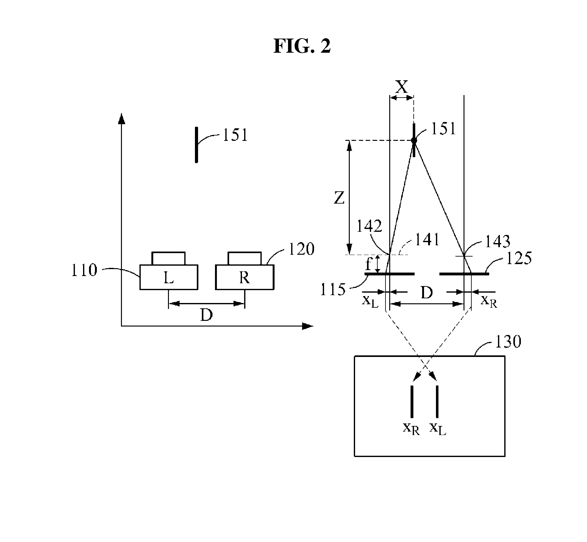
CROSS-REFERENCE TO RELATED APPLICATION[0001]This application claims priority from Korean Patent Application No. 10-2015-0012732, filed on Jan. 27, 2015, in the Korean Intellectual Property Office, the disclosure of which is incorporated herein by reference in its entirety.BACKGROUND[0002]1. Field[0003]Methods and apparatuses consistent with exemplary embodiments relate to determining a disparity or a depth.[0004]2. Description of the Related Art[0005]Stereo matching is a technology of obtaining depth information from images acquired using two cameras. Due to a difference between locations of the two cameras, the same object in two images appears in different locations. A disparity between points focused on sensing planes of the two cameras may be expressed by a function of a focal distance between the two cameras, a distance between the two cameras, a size of a sensing pixel, and a distance to a target object. Based on the above property, whether corresponding pixels between images ...

Claims


Application Information

Patent Timeline
Patent Type & Authority Applications(United States)
IPC IPC(8): G06T7/00H04N13/00G06T7/20
CPCG06T7/0075G06T7/004G06T7/0069G06T7/2093H04N13/0022H04N2013/0085G06T2200/28G06T2207/10012H04N2013/0077H04N2013/0081H04N13/0037G06T2207/10016G06T7/70G06T7/571G06T7/292H04N13/128H04N13/15G06T7/593H04N13/211H04N13/246H04N13/218
Inventor SHIN, CHANGWOOLEE, KYOOBINLEE, JUN HAENGRYU, ERIC HYUNSURKWOO, JOOYEON
Owner SAMSUNG ELECTRONICS CO LTD
Learn More