An extractor tube element

Active Publication Date: 2016-08-04
MICRO MATIC
View PDF0 Cites 1 Cited by
  • Summary
  • Abstract
  • Description
  • Claims
  • Application Information

AI Technical Summary

Benefits of technology

[0004]It is an object of the present invention to wholly or partly overcome the above disadvantages and drawbacks of the prior art. More specifically, it is an object to provide an ext

Problems solved by technology

Since the cleaning is carried out inside the beverage container by for instance flushing and steaming, and the extract

Method used


Image

  • An extractor tube element
  • An extractor tube element
  • An extractor tube element

Examples


Embodiment Construction

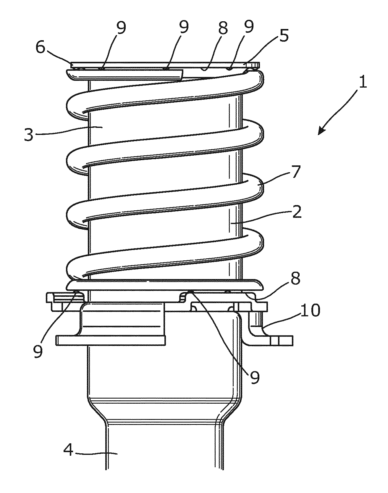
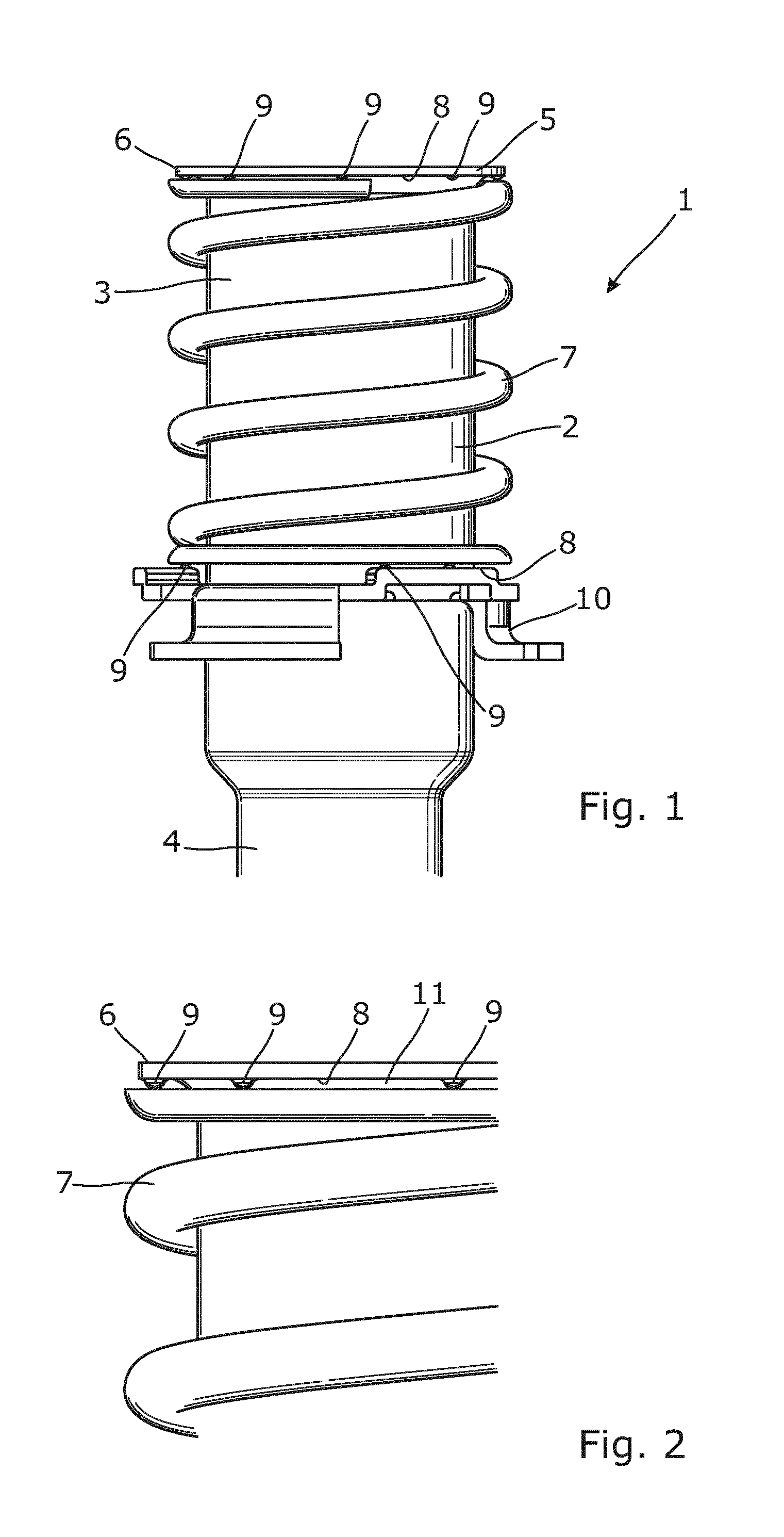
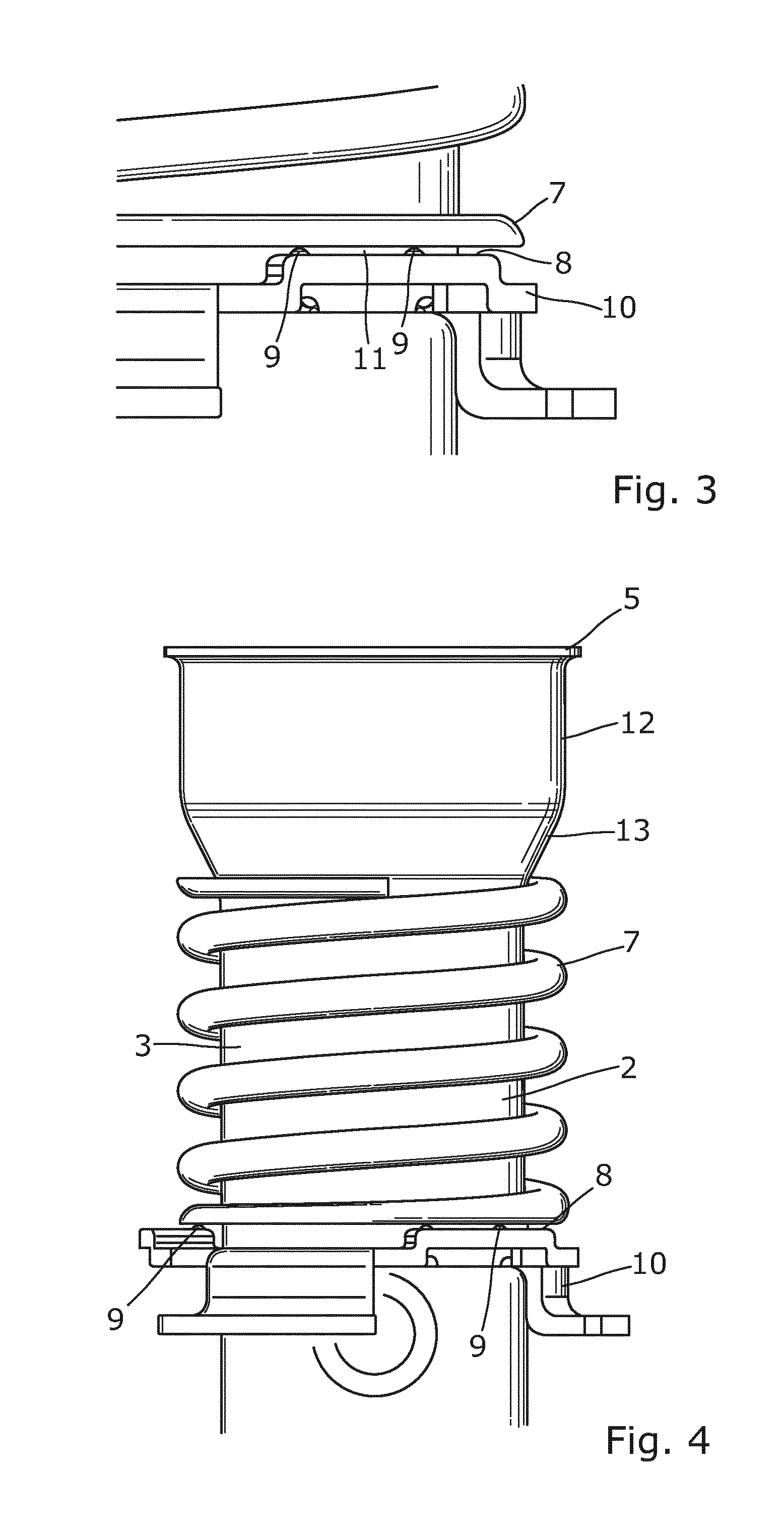
[0047]FIG. 1 shows a part of an extractor tube 1 to be used in an S-system. The extractor tube 1 comprises a down tube 2 having a first tube part 3 and a second tube part 4, the first tube part 3 having a larger diameter than the second tube part 4. At a first end 5 of the down tube 2, a radially projecting flange 6 is arranged. A spring 7 is arranged around the first tube part 3 and abuts the flange 6. The extractor tube element, here in the form of the flange 6, comprises a contact surface 8 which according to the inventive idea has a protrusion 9, the protrusion 9 tapering into a contact point for reducing a contact area of the abutment to the spring 7 and for creating space between the flange 6 and the spring 7. In this embodiment, the flange 6 is projecting out from the first tube part 3 and is surrounding it, so that the flange has a ring-shaped form. Since the spring 7 is adapted to abut a large part of the contact surface 8 of the flange 6, a plurality of protrusions have be...


PUM


Abstract

The present invention relates to an extractor tube element (6, 10, 14) for mounting as a part of an extractor tube (1) for a beverage container (16), comprising a contact surface (8) for abutment to another extractor tube element, wherein the contact surface (8) has a protrusion (9), the protrusion tapering into a contact point for reducing a contact area of the abutment to the other extractor tube element and for creating space between the abutting extractor tube elements. The present invention also relates to an extractor tube (1), a beverage container (16), a beverage dispensing system (100) and a cleaning method.

Description

FIELD OF THE INVENTION[0001]The present invention relates to an extractor tube element for mounting as a part of an extractor tube for a beverage container, comprising a contact surface for abutment to another extractor tube element. The present invention also relates to an extractor tube, a beverage container, a beverage dispensing system and a cleaning method.BACKGROUND ART[0002]When a beverage container has been emptied and is to be refilled with beverage, the inside of the beverage container and the different components present in the beverage container, such as an extractor tube, must be cleaned first in a normal cleaning sequence on a filling line.[0003]However, the known extractor tubes are made up of many different parts which when assembled cooperate with and are movable in relation to each other. Since the cleaning is carried out inside the beverage container by for instance flushing and steaming, and the extractor tubes have many parts, studies have shown that it is diffi...

Claims


Application Information

Patent Timeline
IPC IPC(8): B67D1/08B08B9/08B08B3/10B67D1/07
CPCB67D1/07B08B9/0813B08B3/10B67D1/0802
Inventor RIIS, KEN
Owner MICRO MATIC
Why Eureka
Try Eureka