Vehicle Data and Fuel Management System

a technology of vehicle data and fuel management system, applied in the direction of computer control, instrumentation, electromagnetic radiation sensing, etc., can solve the problems of inability to automatically positively identify the vehicle being fueled, battery is often not rechargeable or replaceable, and achieve the goal of implementing a pro-active vehicle maintenance system

Inactive Publication Date: 2016-08-04
POLLOCK STEPHEN F +3
View PDF14 Cites 21 Cited by
  • Summary
  • Abstract
  • Description
  • Claims
  • Application Information

AI Technical Summary

Benefits of technology

[0019]When a fuel dispensing device is placed in the vehicle's fuel port, the RF / ID tag on the dispensing device receives the query signal from the vehicle-mounted AIM and responds to it. The RF / ID tag on the dispenser provides the Automotive Information Module (AIM) mounted in the vehicle with dispenser identification information and acts as the fueling sequence initiator. Further, the limited short-range coupling between the RF / ID tag and the AIM's fuel port mounted antenna provides security against the misappropriation of fuel (Fuel may only be dispensed while the communication antenna continues to receive responses from the RF / ID tag on the dispenser).

Problems solved by technology

The one common disadvantage of most of the systems is the inability to automatically positively identify the vehicle being fueled.
This leaves open the possibility of a user initiating fueling for an authorized vehicle, but then actually pumping the fuel into an unauthorized vehicle.
The battery is often not rechargeable or replaceable.
However, because an RF / ID tag consumes a small amount of energy in its operation and has a limited service life, it is often possible to provide a battery that will last the service life of the device (such as a 3-year battery).
U.S. Pat. No. 6,618,362 to Terranova discloses a transponder that acts as a replacement for the wire connection at the OBD Port, but does nothing towards implementing a pro-active vehicle maintenance system.

Method used


Image

  • Vehicle Data and Fuel Management System
  • Vehicle Data and Fuel Management System
  • Vehicle Data and Fuel Management System

Examples


Embodiment Construction

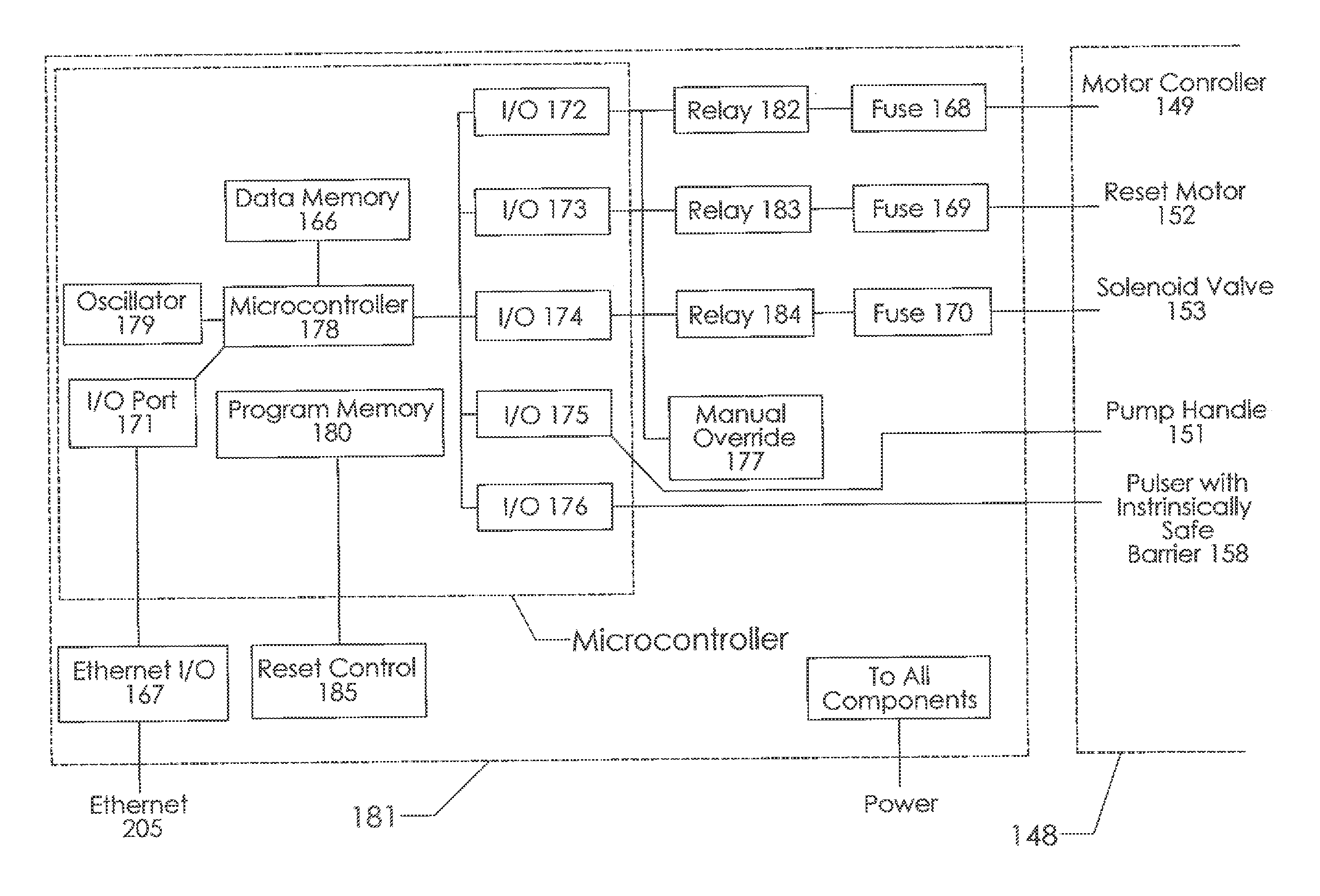
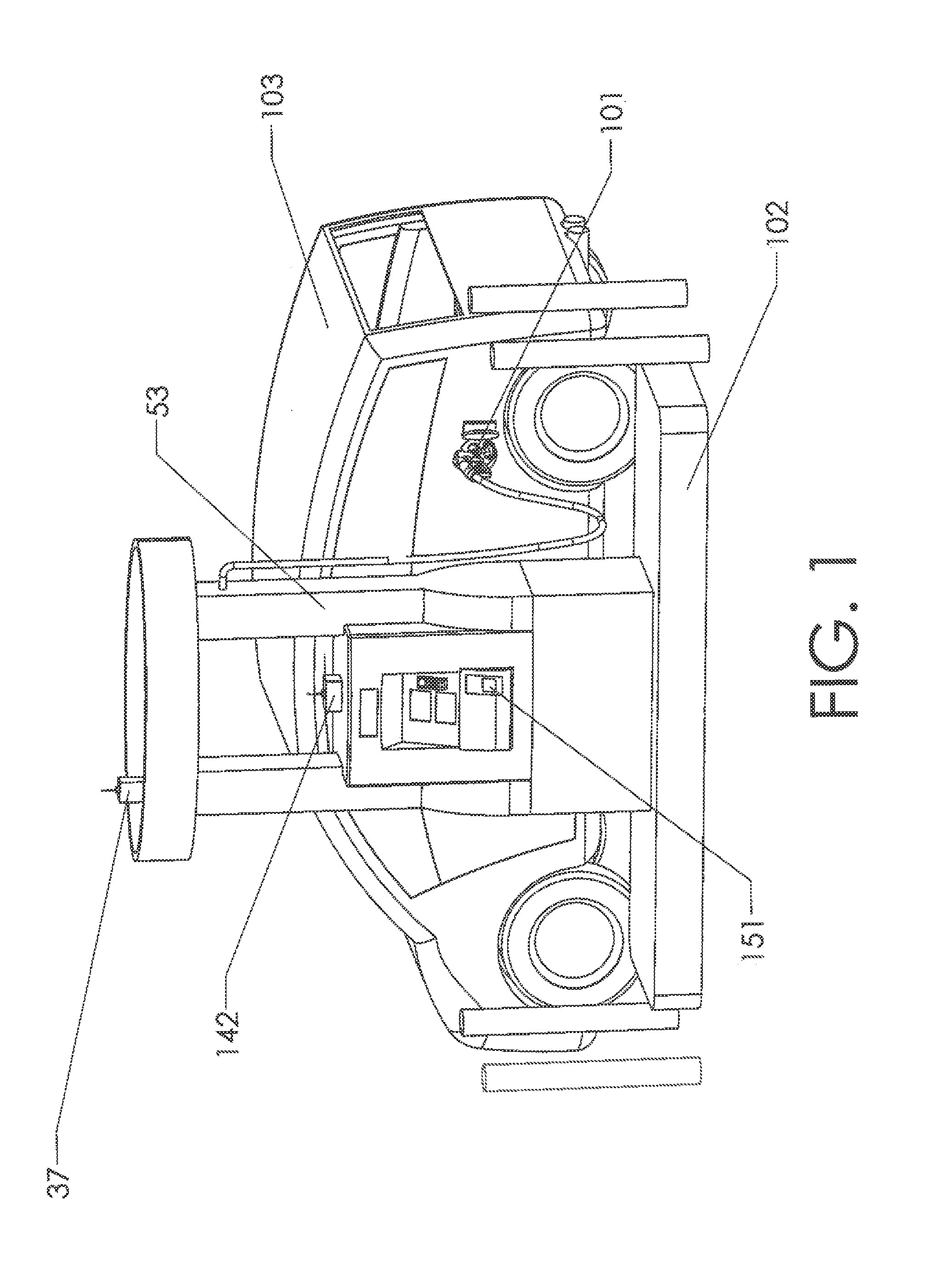
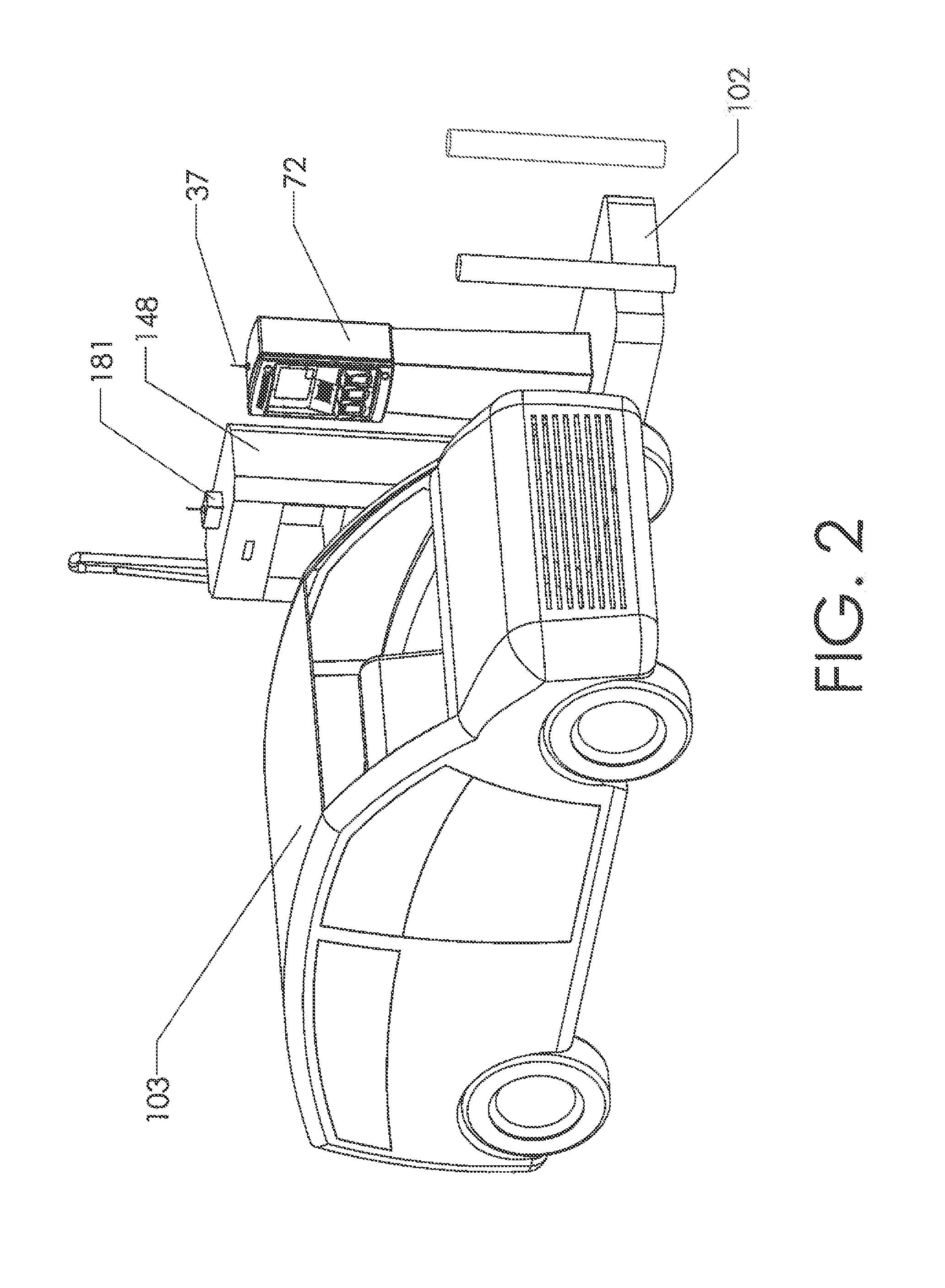
[0188]Practically innumerable embodiments of the present invention are possible. The following descriptions provide details regarding a few of these embodiments. The descriptions pertain to road-going vehicles such as automobiles and trucks. However, the reader should bear in mind that the invention may be adapted for use with other types of vehicles, including aircraft and ships. As stated previously, some of the component names suggest that the inventive system is limited to road-going vehicles (the term “Automotive” being one example). However, the use of this type of name should not be viewed as limiting. Those skilled in the art will realize that a component such as the Automotive Information Module (“AIM”) may easily be adapted for use in an aircraft. Different parameters may be used (such as flight time versus road mileage) but the functions will generally be the same.

[0189]A description of the invention's application to road-going vehicles provides a good basis for the reade...


PUM


Abstract

A system and method for automating dispensing operations such as vehicle fueling operations. The system properly matches a dispenser to a port on a specific container, thereby insuring that the proper substance is loaded into the proper container. A passive or active RF/ID module is attached to the dispenser assembly. A fuel port antenna located on the container's port is used to communicated with this RF/ID module. The fuel port antenna's driving circuitry is able to step through multiple frequencies within a defined frequency band. A suitable transmission frequency is determined and stored in memory. A container-specific frequency is thereby determined and stored for future use. The use of this optimized frequency serves the dual purposes of maintaining only a short-range R/F link while also ensuring the reliability of that link.

Description

BACKGROUND OF THE INVENTION[0001]1. Field of the Invention[0002]This invention relates to the field of vehicle data management and fueling control. More specifically, the invention comprises a system and method for automating vehicle data acquisition and fueling control for a fleet of vehicles. The system and method are suitable for controlling, authorizing and accounting for fuel dispensed from fuel dispensers without requiring control and authorization input from individuals performing the fueling. In addition, the system autonomously collects data from the vehicle being fueled. The disclosed system and method is intended primarily for use in the distribution of liquid and gaseous fuels. However, the system and method may be applied to virtually any product that can be autonomously counted and controlled.[0003]2. Description of the Related Art[0004]Solid state microcontroller-based fuel control and accounting systems have been commercially available since the early 1980s. The know...

Claims


Application Information

Patent Timeline
Patent Type & Authority Applications(United States)
IPC IPC(8): B67D7/04G05B15/02G06K7/10
CPCB67D7/04G05B15/02G06K7/10366B67D7/348
Inventor POLLOCK, STEPHEN FBUTSCH, MARKLEITH, CHRISFUSON, JAMES
Owner POLLOCK STEPHEN F
Why Eureka
Try Eureka