System and Method for Installation of Crown Molding on Imperfect Walls

a crown molding and imperfect technology, applied in the direction of construction, building construction, etc., can solve the problems of difficult to determine the angle of precision cutting, the hole and mark where the nails are, and the inability to satisfactorily install traditional moldings

Active Publication Date: 2016-08-04
HOFFMAN JEREMY P +1
View PDF18 Cites 10 Cited by
  • Summary
  • Abstract
  • Description
  • Claims
  • Application Information

AI Technical Summary

Benefits of technology

[0010]The present invention provides an improved system and method for installation of crown molding that offers ease of installation compared to traditional crown molding installation, and also offers improvements that allow for secure installation of crown molding against a wall that contains irregularities and deviations from the intended plane. The invention comprises an installation portion and a molding portion, where the decorative face of the molding is entirely within the molding portion. The crown molding is installed by securing the attachment portion, which is above the center of mass of the entire molding system, firmly against a wall or vertical surface. The invention permits the attachment portion to flex as needed as it is firmly secured to the wall with its irregularities, without transmitting those irregularities, especially over short distances, to the decorative face. Since some wall irregularities may result in the lower edge of the decorative face being displaced away from the wall, the invention also incorporates a hinge-like flex either within the attachment portion, or at the junction of the attachment portion and the molding portion, which creates a pivot enabling a simple pendulum system that allows the lower edge of the decorative face fall into place at the wall, constantly urged by gravity acting on the simple pendulum system. The rear of the molding portion may also have a relief space above where the lower portion contacts the wall to prevent any protruding wall irregularities from forcing the lower edge of the decorative face away from the all.

Problems solved by technology

This installation method, however, leaves holes and marks where the nails travel through the decorative face, requiring patching to regain a smooth surface on the decorative face.
Further, installing traditional crown molding where walls meet in the corners of a room is a known carpentry challenge, with precision cuts at difficult to determine angles required.
The difficulty of satisfactorily installing traditional crown molding in corners is one of the reasons that installing traditional crown molding is considered one of the most difficult trim work installations.
The result is a molding that appears straight to the eye, even if it is installed on a wall (and ceiling) with surface irregularities.
Traditional wood crown molding that is installed over middle length irregularities (such as a waviness over a distance of one foot as an example) will not be able to flex and tightly follow the wave of the wall, but will remain largely straight against such middle-length waves.
This may leave gaps where the molding remains straight against the wave, which gaps are conventionally filled with caulk to obscure the gap.
However, certain wall irregularities would cause such crown molding system to install in an undesirable fashion.
Further, the crown molding has no provisions for separable flex of the attachment portion, causing wall irregularities to be transmitted to the decorative face.

Method used


Image

  • System and Method for Installation of Crown Molding on Imperfect Walls
  • System and Method for Installation of Crown Molding on Imperfect Walls
  • System and Method for Installation of Crown Molding on Imperfect Walls

Examples


Embodiment Construction

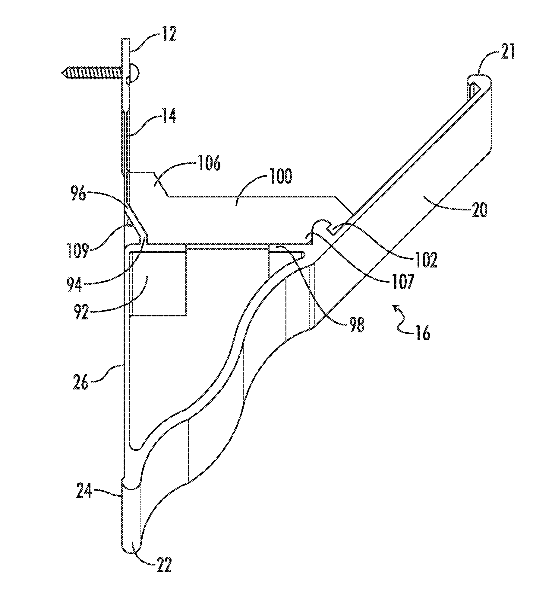
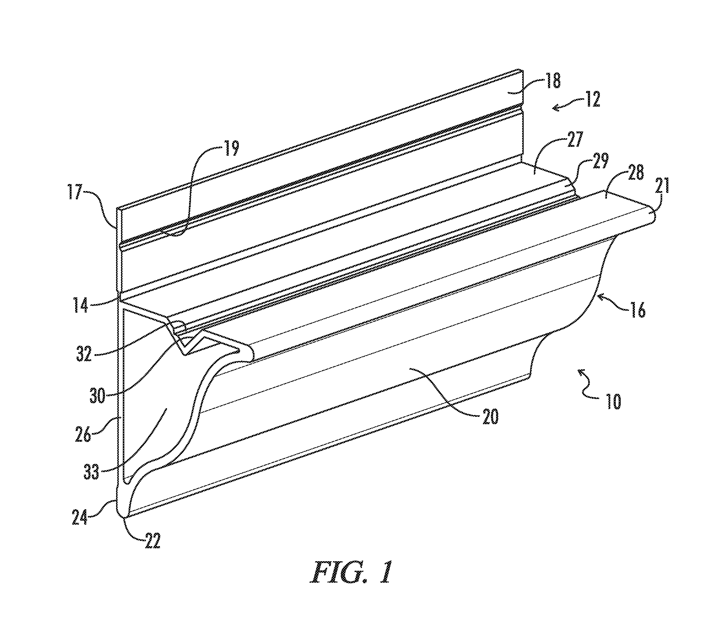
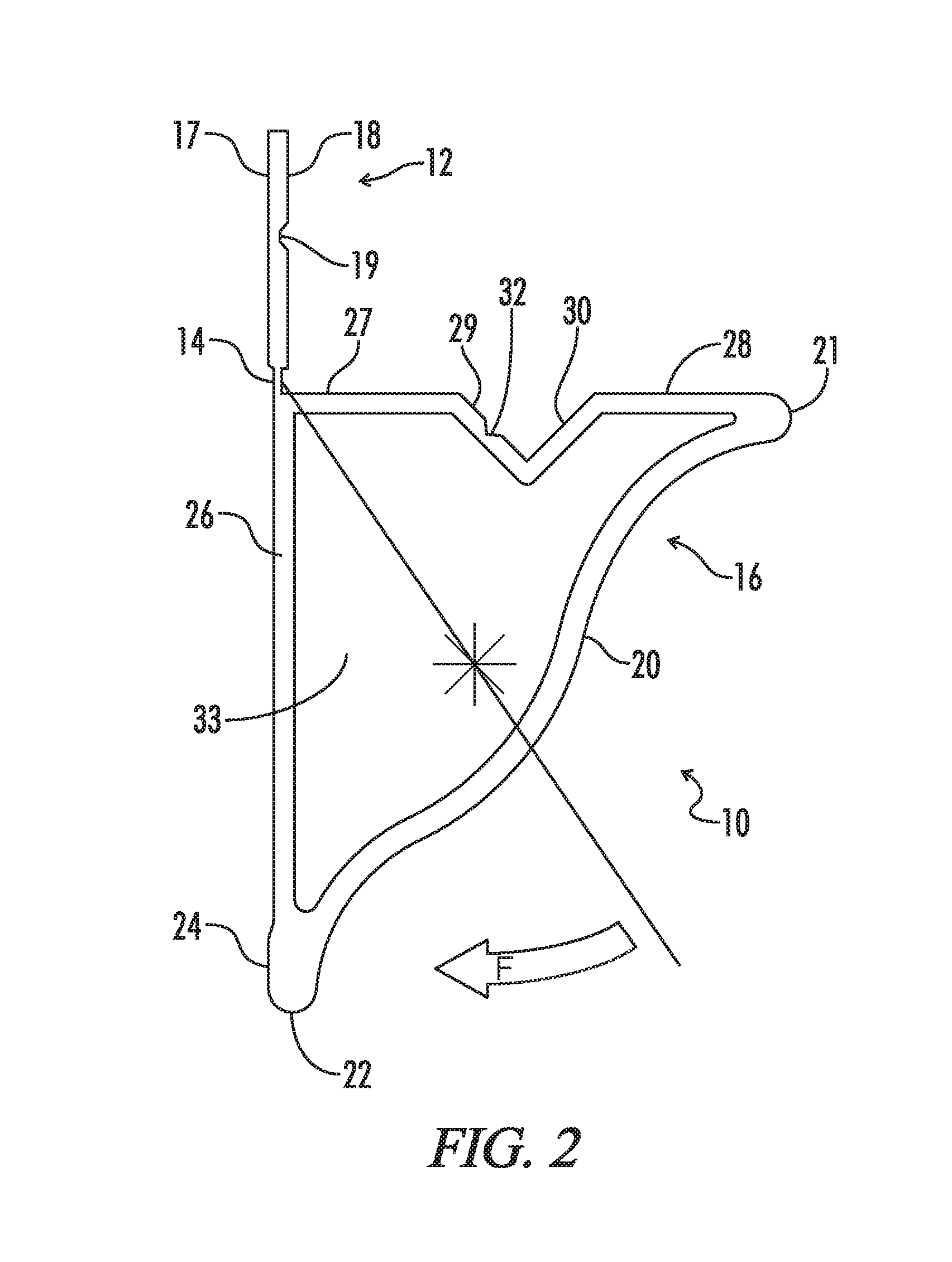
[0029]The following detailed description is of the best mode or modes of the invention presently contemplated. Such description is not intended to be understood in a limiting sense, but to be a non-limiting example of the invention presented solely for illustration thereof, and by reference to which in connection with the following description and the accompanying drawings one skilled in the art may be advised of the advantages and construction of the invention. Wherever possible, like reference numbers have been utilized to refer to like elements or features of the invention throughout the different embodiments illustrated herein.

[0030]The present molding system is adapted for use with an irregular wall. By irregular wall, what is meant is a wall that has variations from its designed plane (if referring to a curved wall, then variations from that curved design). These variations are known to exist in all walls, even under excellent construction conditions, and may be present in new...


PUM


Abstract

A molding system installed at or near the top of a vertical wall having a molding portion and an attachment portion, where the attachment portion is attached securely to the wall above at least the center of mass of the molding portion, and the molding portion has an outwardly visible decorative face which extends down to where the lower edge of the molding portion meets the wall. The attachment portion is enabled to flex as it is firmly attached to an imperfect wall, and the structure of the molding portion is such that the decorative face of the molding system remains preferentially straight and preferentially positioned as the molding system is installed on an irregular wall. A hinge-like flex is enabled along the length of the molding above the center of mass of the molding portion such that the decorative face of the molding can pivot like a pendulum ensuring the lower edge of the molding is placed against the wall. None of the methods of installation of this system violate the decorative face of the molding and a consistent decorative face profile extends around the entire installation.

Description

CROSS REFERENCE TO RELATED APPLICATIONS[0001]This application claims priority to provisional application No. 62 / 109,443 filed on Jan. 29, 2015, provisional application No. 62 / 128,273 filed on Mar. 4, 2015, and also provisional application No. 62 / 183,956 filed on Jun. 24, 2015, the contents of which are incorporated herein by reference in their entireties.FIELD OF THE INVENTION[0002]The present invention is directed to systems and methods for installing crown molding in a building, and more particularly to a molding assembly and method of installation that speeds the process and is particularly suited to spaces where walls, and junctions of walls, are imperfect and vary from the true geometric planes that were intended. The present invention is also suited to various applications where the molding may bear weight in addition to its own, such as supporting a suspended ceiling or supporting various electrical equipment.BACKGROUND OF THE INVENTION[0003]Crown molding is a desirable desig...

Claims


Application Information

Patent Timeline
Patent Type & Authority Applications(United States)
IPC IPC(8): E04F19/04
CPCE04F19/0436E04F2019/0431E04F19/0459E04F19/0486E04F2019/0422E04F2019/0427
Inventor HOFFMAN, JEREMY P.MACMILLAN, ROBERT
Owner HOFFMAN JEREMY P
Why Eureka
Try Eureka