
Method for the manufacture of a plastic component, plastic component, and shoe

a technology of plastic components and manufacturing methods, applied in the field of plastic components, can solve the problems of affecting the stability and cooling of the fused component, the limited shape of the possible manufacturing components, and the loss of a large part of the steam energy stored in the mold

Active Publication Date: 2016-08-11
ADIDAS
View PDF4 Cites 98 Cited by
  • Summary
  • Abstract
  • Description
  • Claims
  • Application Information

AI Technical Summary

Benefits of technology

This patent describes a way to make plastic parts that can have specific properties in specific parts of the part. This can be done without needing a complicated manufacturing device. The method is also energy-efficient and environmentally friendly, and can be done quickly. It can be used for mass production and can be automated to create different types of plastic parts.

Problems solved by technology

Common to the methods known from the prior art is, however, that the processing of the base material to dimensionally stable components of a high quality is often only possible up to a certain thickness or a certain packing density, meaning that the possible shapes of components that can be manufactured may be limited.
For a liquid binder material or heat energy supplied by steam, this is only possible to a limited degree for thicker components and / or may lead to imperfections, because “channels” or “inlet openings” are provided in the component to allow the binder or the steam to homogeneously infuse the base material within the mold.
Moreover, in particular when using steam as an energy carrier, it turns out to be disadvantageous that a major share of the energy stored within the steam may be lost in the mold instead of being supplied to the particles / particle surfaces.
This can, on the one hand, necessitate a long preheating phase until the mold is heated up to a saturation temperature, and can, on the other hand, delay stabilization and cooling of the fused component since the mold may have stored a large amount of heat energy that delays cooling.
Therefore, the method can be protracted and very energy inefficient.

Method used


Image

  • Method for the manufacture of a plastic component, plastic component, and shoe
  • Method for the manufacture of a plastic component, plastic component, and shoe
  • Method for the manufacture of a plastic component, plastic component, and shoe

Examples


Embodiment Construction

[0081]The subject matter of embodiments of the present invention is described here with specificity to meet statutory requirements, but this description is not necessarily intended to limit the scope of the claims. The claimed subject matter may be embodied in other ways, may include different elements or steps, and may be used in conjunction with other existing or future technologies. This description should not be interpreted as implying any particular order or arrangement among or between various steps or elements except when the order of individual steps or arrangement of elements is explicitly described.

[0082]Possible embodiments of the inventive method are described in the following detailed description primarily with respect to cushioning elements for sports apparel, in particular soles for shoes. It is, however, emphasized that the present invention is not limited to these embodiments. To the contrary, it may also be used for plastic components for the automotive industry, f...


PUM

PropertyMeasurementUnit
Ratioaaaaaaaaaa
Frequencyaaaaaaaaaa
Energyaaaaaaaaaa

Abstract

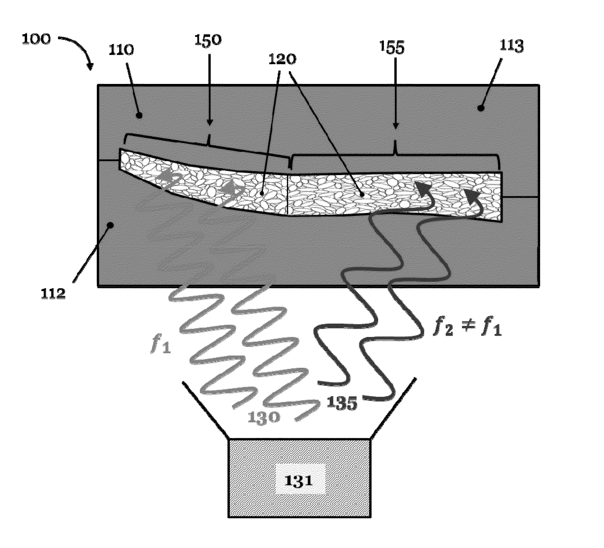
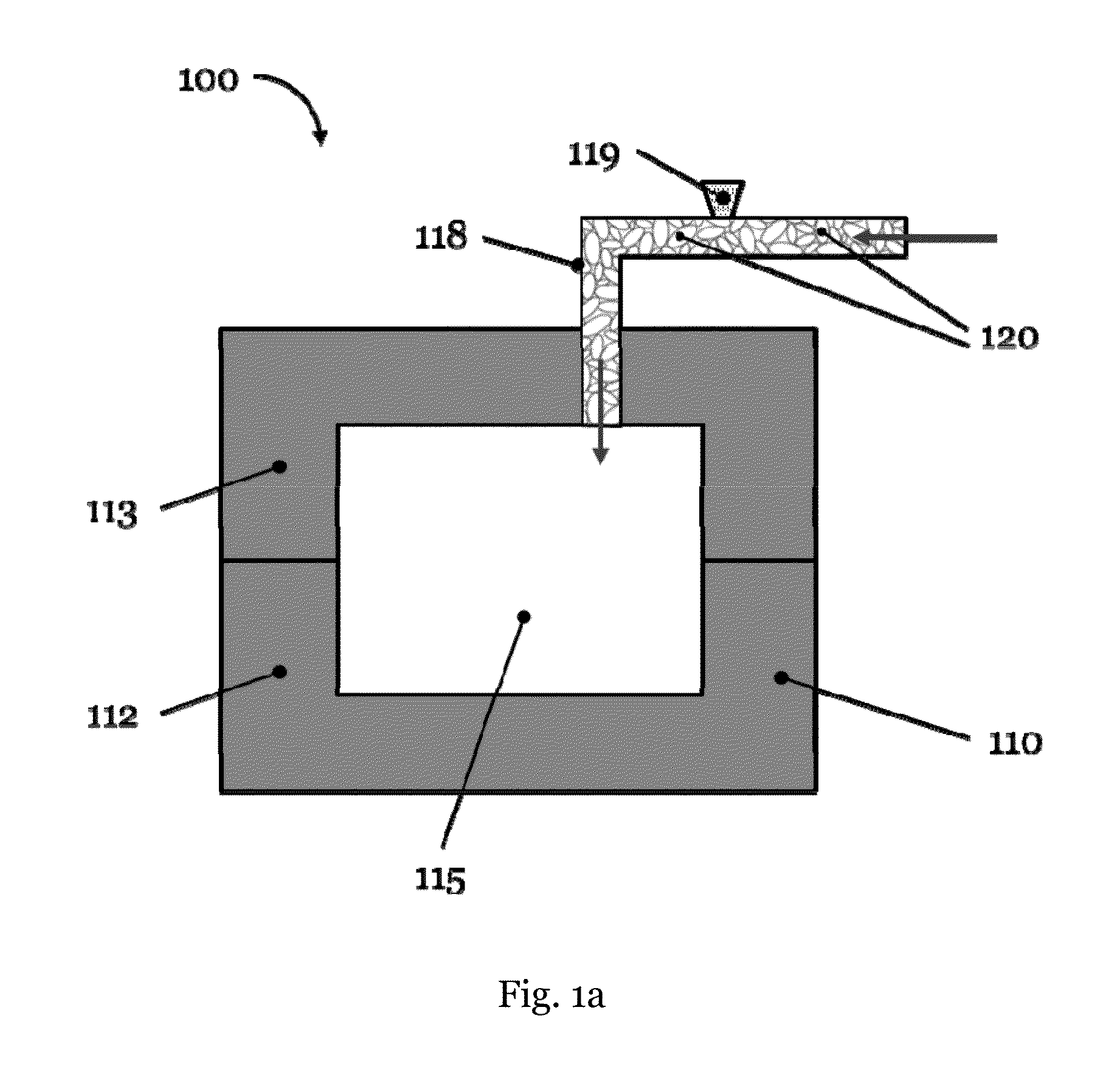
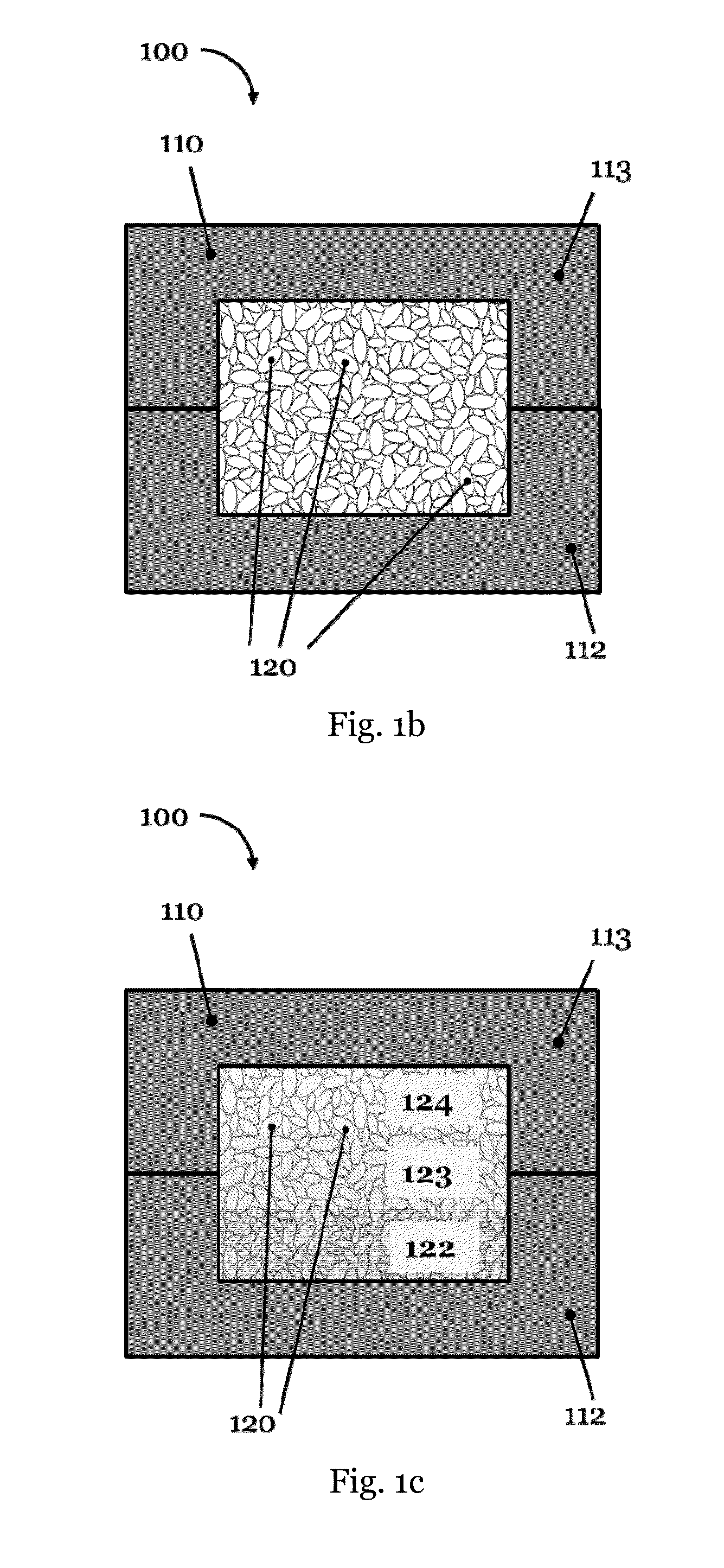
Described are methods for manufacturing a plastic component, in particular a cushioning element for sports apparel, a plastic component manufactured with such methods, for example a sole or a part of a sole for a shoe, and a shoe with such a sole. The method for the manufacture of a plastic component includes loading a mold with a first material includes particles of an expanded material and fusing the surfaces of the particles by supplying energy. The energy is supplied in the form of at least one electromagnetic field.

Description

CROSS REFERENCE TO RELATED APPLICATION[0001]This application is related to and claims priority benefits from German Patent Application No. DE 10 2015 202 013.4, filed on Feb. 5, 2015, entitled METHOD FOR THE MANUFACTURE OF A PLASTIC COMPONENT, PLASTIC COMPONENT, AND SHOE (“the '013 application”), and is related to and claims priority benefits from European Patent Application No. EP 16 151 732.1, filed on Jan. 18, 2016, entitled METHOD FOR THE MANUFACTURE OF A PLASTIC COMPONENT, PLASTIC COMPONENT, AND SHOE (“the '732 application”). The '013 and '732 applications are hereby incorporated herein in their entireties by this reference.FIELD OF THE INVENTION[0002]The present invention relates to a method for the manufacture of a plastic component, in particular a cushioning element for sports apparel, a plastic component manufactured with such a method, for example a sole or part of a sole for a shoe, as well as a shoe with such a sole.BACKGROUND[0003]Nowadays, plastic components play an e...

Claims


Application Information

Patent Timeline
IPC IPC(8): A43B7/32C08J9/38B29D35/12A43B5/06A41D13/015
CPCB29L2031/504C08J9/38B29C67/205A41D13/015C08J2375/04C08J2371/00C08J2367/04C08J2367/02C08J2377/00B29K2995/0037B29K2105/251B29D35/12A43B7/32A43B5/06B29C35/08A43B5/00A43B13/187B29C35/0805B29C44/3415B29C44/445B29D35/128B29D35/142B29D35/148B29C2035/0811B29C2035/0822B29C2035/0827B29C2035/0855B29C2035/0861A43B13/04A43B13/125B29D35/122B29K2067/003B29K2067/006B29K2067/046B29K2075/00B29L2009/00B29K2101/12
Inventor LE, TRU HUU MINHHOLMES, CHRISTOPHER EDWARDROBERTSON, CHRISTOPHERKURTZ, MAXIMILIAN PHILIPPROMANOV, VICTOR
Owner ADIDAS
Learn More