Welding jig for pedicle screw, welding apparatus for pedicle screw and welding method for pedicle screw using the same

Inactive Publication Date: 2016-08-11
MOON SOO JUNG +1
View PDF5 Cites 1 Cited by
  • Summary
  • Abstract
  • Description
  • Claims
  • Application Information

AI Technical Summary

Benefits of technology

[0019]Embodiments of the present disclosure are capable of preventing deformation of the welding regions of the screw head and the wing that is caused by high-temperature heat applied during welding, as the welding of the screw head and the wing is carried out after firmly locking them to a jig.
[0020]Moreover, unlike the conventional laser welding, the contact regions of the screw head and the wing in the present disclosure are melted and welded as

Problems solved by technology

While the screw can be integrally manufactured through machining, machining has problems of high defect rate and material loss.
However, laser welding has a limitation in that only the laser-irradiated reg

Method used


Image

  • Welding jig for pedicle screw, welding apparatus for pedicle screw and welding method for pedicle screw using the same
  • Welding jig for pedicle screw, welding apparatus for pedicle screw and welding method for pedicle screw using the same
  • Welding jig for pedicle screw, welding apparatus for pedicle screw and welding method for pedicle screw using the same

Examples


Example

[0028]Hereinafter, embodiments of the present disclosure are described in detail with reference to FIGS. 1-6. Regarding the reference numerals assigned to the elements of each figure, it should be noted that identical elements were assigned the same numerals whenever possible, even when appearing in different figures. In addition, detailed descriptions of known features or functions related to the present disclosure were omitted if it was determined that they might obscure the essentials of the present disclosure.

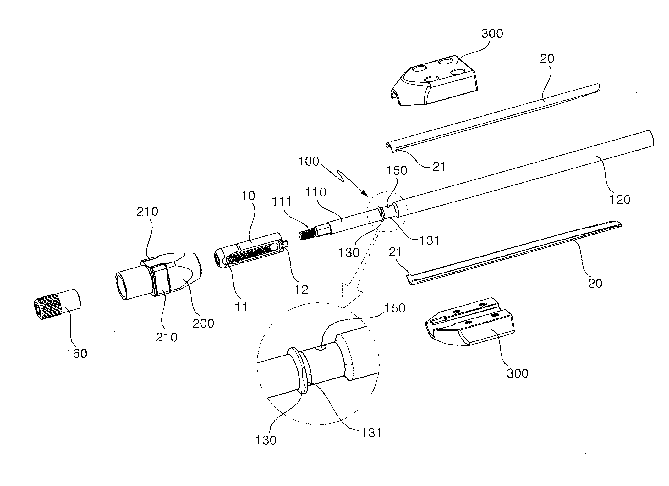
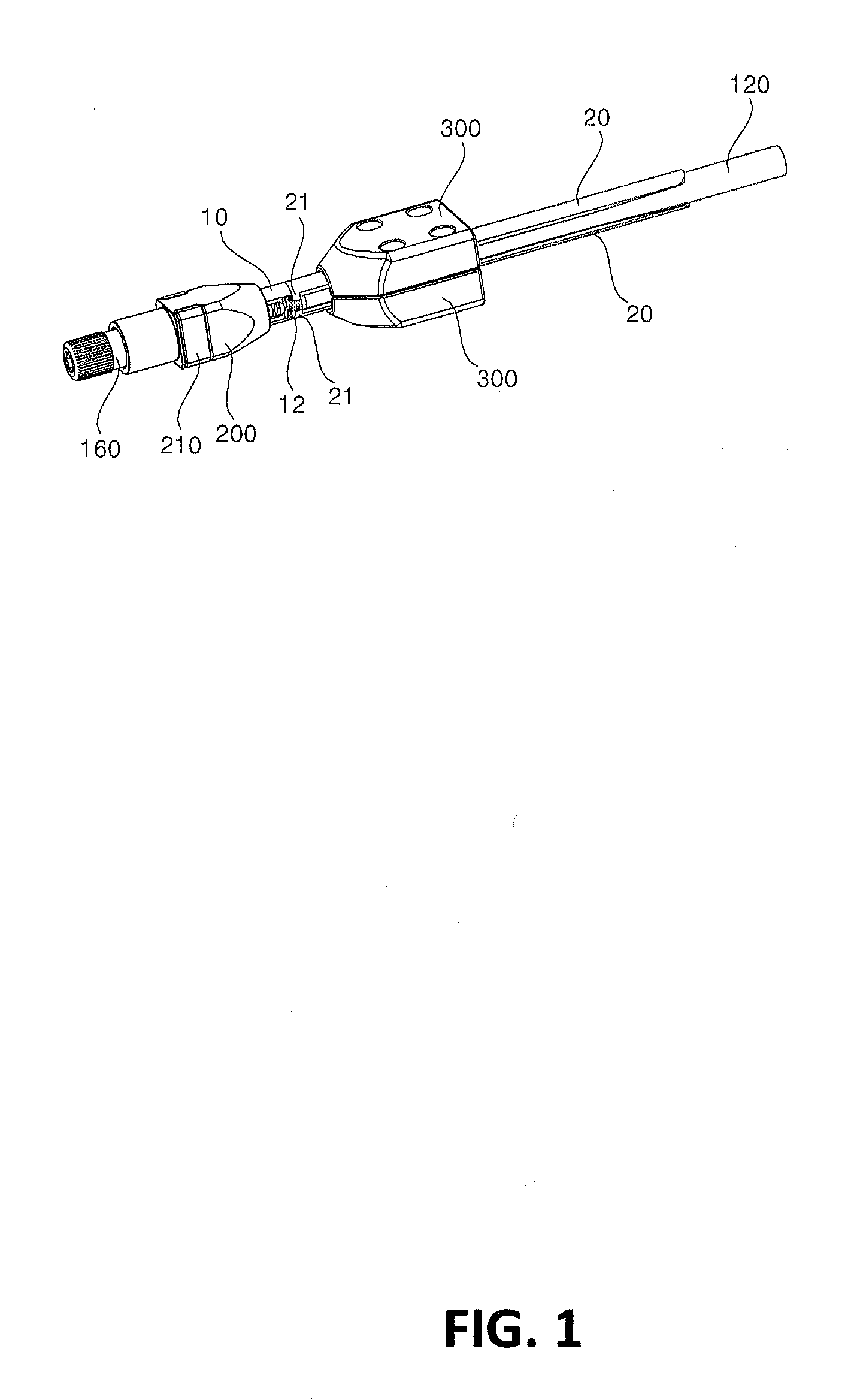
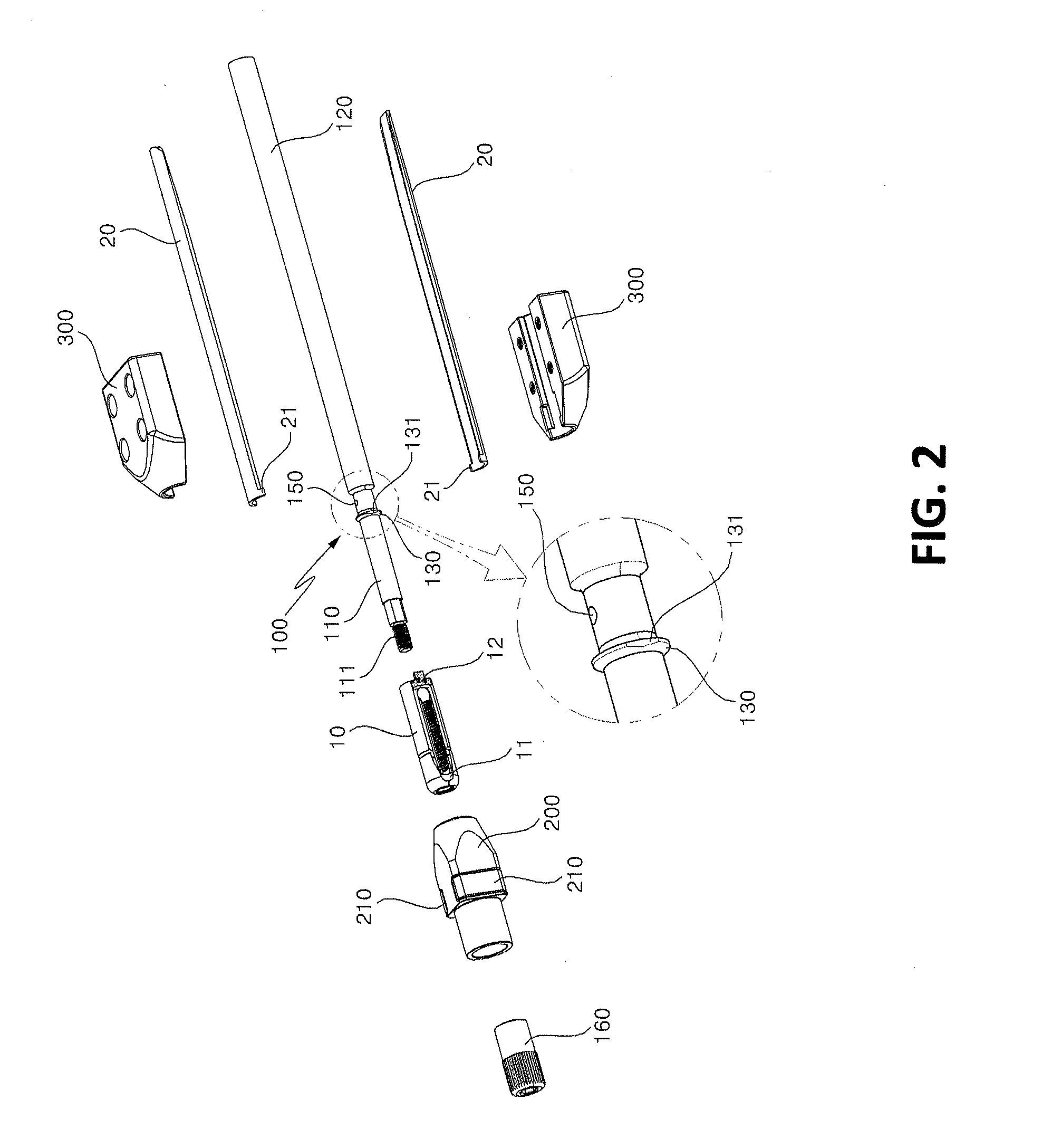
[0029]FIG. 1 is a perspective view illustrating the overall structure of a welding jig for pedicle screw according to an embodiment of the present disclosure. FIG. 2 is an exploded perspective view of a welding jig for pedicle screw according to an embodiment of the present disclosure.

[0030]As illustrated in FIG. 1 and FIG. 2, a welding jig for pedicle screw according to the present disclosure comprises a jig core (100), a head holder (200), and a wing holder (300).

[0031]Th...


PUM

PropertyMeasurementUnit
Currentaaaaaaaaaa
Electric potential / voltageaaaaaaaaaa
Angular velocityaaaaaaaaaa

Abstract

A welding jig for pedicle screw has a jig core, a head holder, and a pair of wing holders. The jig core includes a first mounting part inserted into a screw head of a pedicle screw, and a second mounting part to which a pair of wings to be welded to the screw head are attached to an outer surface thereof. The head holder covers the screw head and locks the screw head to the first mounting part, and the pair of wing holders covers the pair of wings and locks the pair of wings to the second mounting part by being coupled to each other. A welding apparatus for pedicle screw includes the welding jig for pedicle screw, a turntable, and a welding torch. The turntable has the jig locked thereto, and the welding torch applies power to the welding regions of the wings and the screw head.

Description

CROSS-REFERENCE TO RELATED APPLICATIONS[0001]This Application claims the benefit of priority to Korean Patent Application No. 10-2015-0020781 filed on Feb. 11, 2015, which is incorporated by reference in its entirety.FIELD OF THE INVENTION[0002]The present disclosure relates to a welding jig for pedicle screw, a welding apparatus for pedicle screw, and a welding method for pedicle screw using the same, which allow precise and stable welding of the screw head and the wing of a pedicle screw.BACKGROUND OF THE INVENTION[0003]Spondylopathy generally refers to a disorder in which pain is induced by pressure exerted on the nerves adjacent to the vertebral column as a result of narrowed space between the vertebrae due to degeneration of the bones, ligaments, muscles, etc. or as a result of spinal deformity caused by poor posture.[0004]Therefore, in patients with a partially damaged or injured spine, an artificial aid is used to fasten the adjacent spinal sections such that the injured sect...

Claims


Application Information

Patent Timeline
IPC IPC(8): B23K37/04B23K31/02
CPCB23K31/02B23K37/0426B23K37/0443B23K9/0026
Inventor MOON, SOO JUNGSEO, IL SEOP
Owner MOON SOO JUNG
Why Eureka
Try Eureka