
Tine harrow

a technology of tine harrow and tine harrow, which is applied in the direction of agricultural machinery, agricultural tools and machines, adjusting devices, etc., can solve the problems of reducing the effectiveness of the tine harrow in changing land conditions, and reducing the likelihood of getting stuck in wet soil conditions, so as to enhance the effectiveness of the response of the tine harrow and the effect of effective respons

Active Publication Date: 2016-08-18
SALFORD GRP INC
View PDF2 Cites 14 Cited by
  • Summary
  • Abstract
  • Description
  • Claims
  • Application Information

AI Technical Summary

Benefits of technology

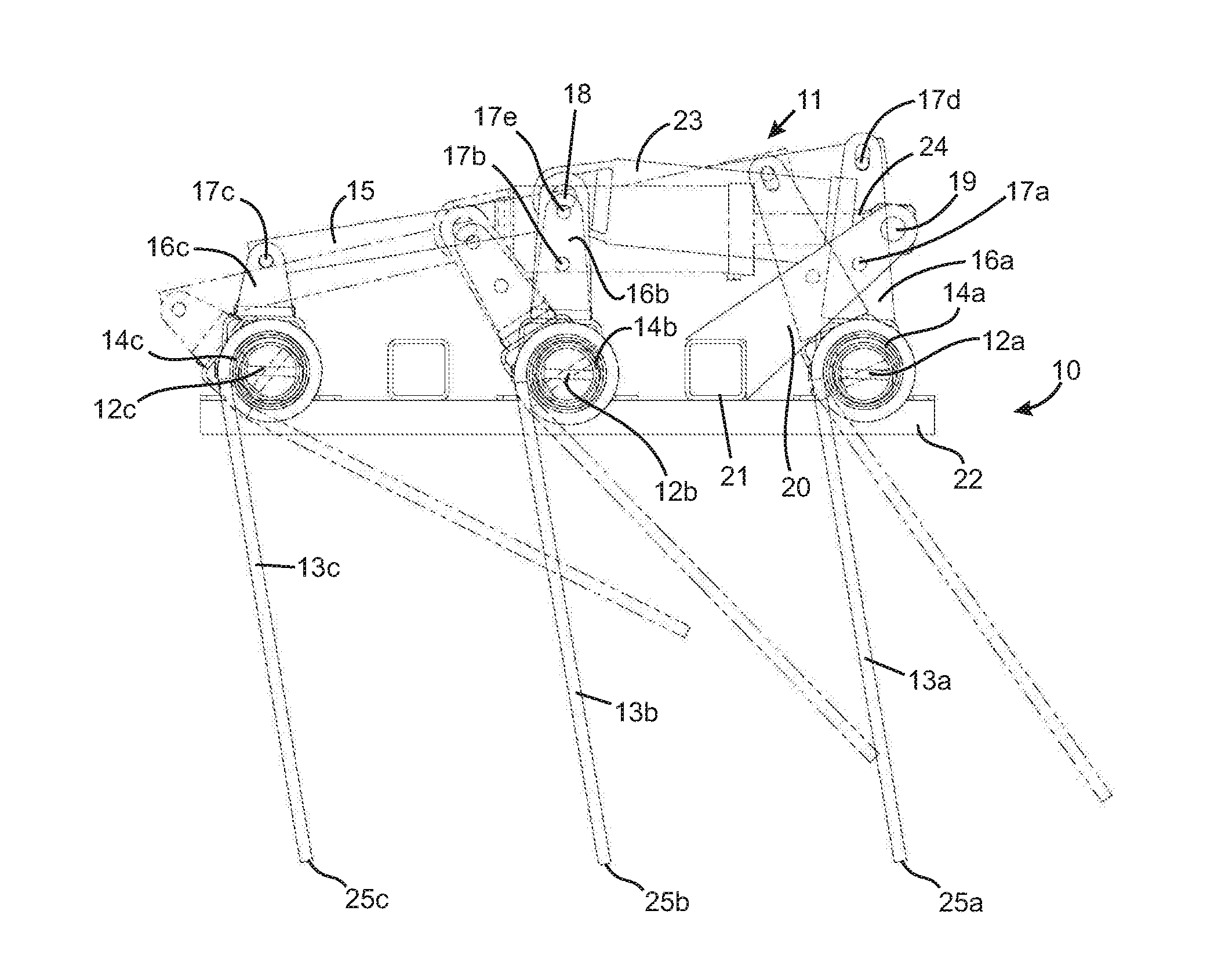
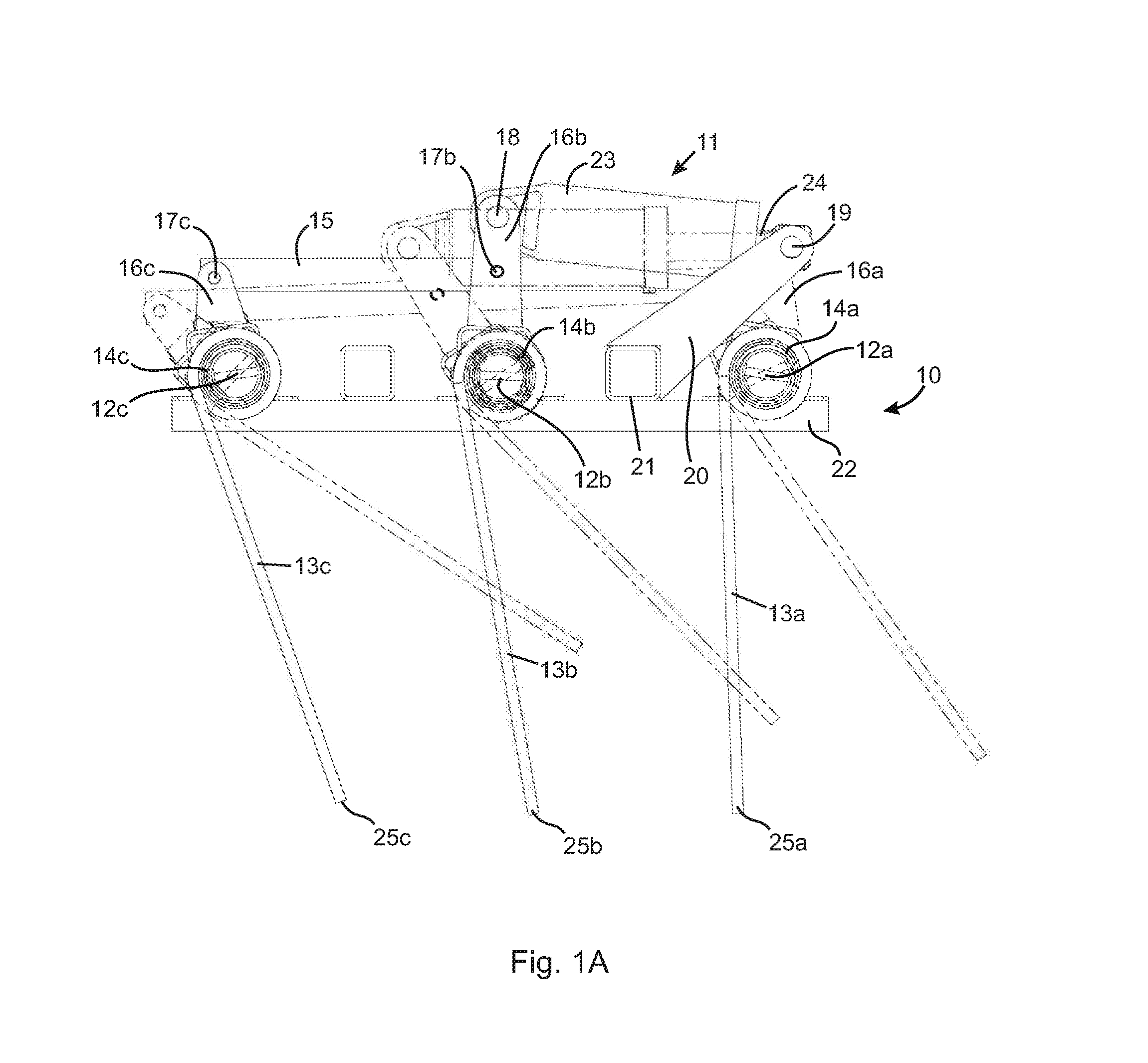
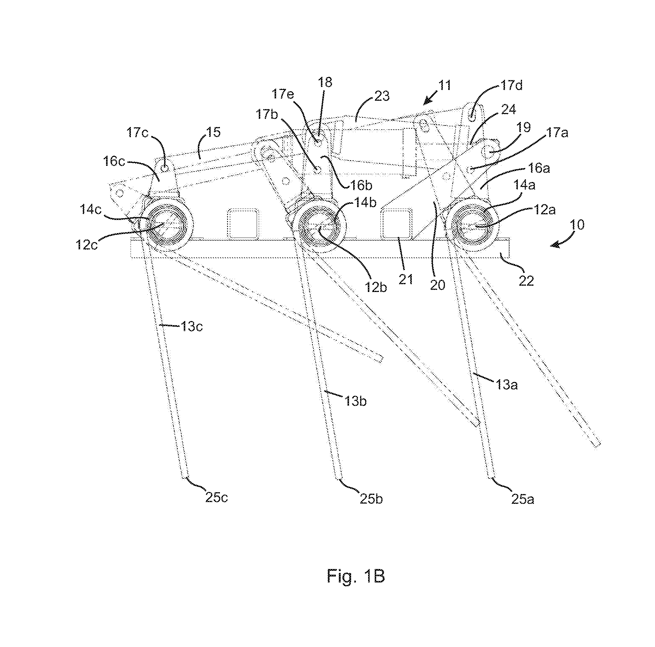
The invention provides the ability to adjust the position of individual tones or rows of tones in a tine harrow in response to changing land conditions. This allows the tines to interact with the field more or less aggressively, depending on the position they are set in. By selectively setting the position of the tines, multiple positions can be chosen to enhance the response of the harrow to changing conditions. This also allows for control over down-pressure, which affects whether residue is let through the harrow or not. Overall, this invention improves the effectiveness of the tine harrow and enhances its ability to adapt to different land conditions.

Problems solved by technology

Operating at such faster speeds causes the crop residue to be cut more finely and reduces the likelihood of becoming stuck in wet soil conditions.
However, operating at faster speeds, especially above 12 miles per hour, can create significant problems with leveling attachments being dragged behind the cultivator frame.
However, prior art apparatuses do not permit independent control of each tine or at least a single row of tines, which limits the effectiveness of the tine harrow in changing land conditions.

Method used


Image

  • Tine harrow
  • Tine harrow
  • Tine harrow

Examples


second embodiment

[0044]FIG. 6 illustrates how relative positions of tines of a tine harrow in relation to a surface of a field may be selectively controlled. In FIG. 6, the harrow section 10 has three transverse rows 12a, 12b, 12c of harrow tines 13a, 13b, 13c rigidly mounted on respective transverse rotatable axles 14a, 14b, 14c as described in connection with FIG. 1A. Mounted concentrically on the transverse axles 14a, 14b, 14c are toothed pinions 106a, 106b, 106c, respectively, which rotate with the transverse axles 14a, 14b, 14c. A longitudinally-oriented elongated translatable toothed rack 105 is configured so that the teeth of the rack 105 mesh with the teeth of the pinions 106a, 106b, 106c. The teeth of the toothed rack 105 also mesh with teeth of a drive gear 184 mounted on a drive shaft 183 of a motor 181. Rotation of the drive shaft 183 by the motor 181 causes rotation of the drive gear 184, which causes the toothed track 105 to translate longitudinally. Longitudinal translation of the too...

third embodiment

[0045]FIG. 7 illustrates how relative positions of tines of a tine harrow in relation to a surface of a field may be selectively controlled. The embodiment depicted in FIG. 7 is similar to the one in FIG. 6 except that the toothed rack is replaced with an endless loop drive chain 185. The drive chain 185 meshes with the teeth of the pinions 106a, 106b, 106c and with the teeth of the drive gear 184. The chain 185 may be driven in either direction to lower and raise the tines 13a, 13b, 13c. Operation of the embodiment in FIG. 7 is essentially the same as the one described in connection with FIG. 6.


PUM


Abstract

A tine harrow has a plurality of harrow tines mounted on and downwardly depending from a harrow frame. The tines are configured to be moveable between a lowered position and a raised position, and at least one tine lowerable or raiseable to a different relative position in relation to a surface of a field than others of the tines. The ability to lower and raise individual tines or rows of tines to different positions in relation to a surface of a field provides more effective response of the tine harrow to changing land conditions. The positions to which individual tines or rows of tines are lowered or raised may be selectively set to further enhance effectiveness of the response of the tine harrow to changing land conditions.

Description

CROSS-REFERENCE TO RELATED APPLICATIONS[0001]This application claims the benefit of United States Provisional Patent Application Ser. No. 62 / 114,242 filed Feb. 10, 2015, the entire contents of which is herein incorporated by reference.FIELD OF THE INVENTION[0002]The present invention relates to an apparatus, system and method for tilling a field. In particular, the present invention relates to control of a tine harrow, especially as part of an apparatus, system and method for a conservation tillage strategy.BACKGROUND OF THE INVENTION[0003]Apparatuses, systems and methods for tilling agricultural fields are very well known in the art. Apparatuses typically comprise a cultivator frame having multiple and various tilling attachments attached thereto, laid out on the frame in a variety of patterns to maximize the desired tilling effect. The apparatus is dragged behind a vehicle during the tilling operation.[0004]In particular, conservation tillage, or vertical tillage as it is sometime...

Claims


Application Information

Patent Timeline
Patent Type & Authority Applications(United States)
IPC IPC(8): A01B63/24A01B19/02A01B19/10A01B63/00
CPCA01B63/24A01B19/10A01B19/02A01B63/008
Inventor GRAY, GEOF J.AVERINK, JOHN MARKGILLIER, JONATHANBAKER, BRADLEY WILLIAM
Owner SALFORD GRP INC
Learn More