Cabinet Levelling Apparatus

a technology for levelling equipment and cabinets, which is applied in the direction of machine supports, manufacturing tools, furniture parts, etc., can solve the problems of difficult adjustment of the foot located at the rear of the cabinet or the appliance, time-consuming, and difficult to achieve alignmen

Active Publication Date: 2016-08-18
DESIGNERSCOPE LTD
View PDF0 Cites 24 Cited by
  • Summary
  • Abstract
  • Description
  • Claims
  • Application Information

AI Technical Summary

Benefits of technology

[0044]In some embodiments the tool comprises two lateral extensions forming a jaw for capturing a diameter of the coupling to releasably retain the tool to the coupling in a lateral direction to releasably maintain engagement between the driving member and the driven member or feature when the driving member drives the driven member for height adjustment of the leg.
[0060]In some embodiments the driven member or feature is a rotary rack facing upwards and the driving member is a pinion, and the thread of the shaft or the socket is a right hand thread so that rotation of the pinion in a clockwise direction about a lateral axis rotates the threaded shaft to increase the height of the cabinet, appliance or structure.
[0121]In some embodiments the tool is adapted to remain continuously engaged with the coupling when the driving member drives the driven member or feature to rotate about the longitudinal axis of the leg in both directions so that the direction of height adjustment of the height adjustable leg can be reversed without removing the tool from the coupling.
[0167]In some embodiments the tool is adapted to displace relative the floor to reach each of said feet to engage with said driven member and drive said driven member without needing to rotate about a longitudinal axis of the foot.
[0168]In some embodiments the tool is adapted to slide along the floor to reach and be aligned with each of said feet to engage with said driven member and drive said driven member without needing to slide relative the floor or rotate about a longitudinal axis of the foot.

Problems solved by technology

This can be time consuming and alignment may not be easy to achieve each time the tool is to be re-engaged.
Adjustment of a foot located at the rear of a cabinet or appliance may be difficult, as an extra long tool handle may be required to reach the back feet from the front of the cabinet, such that the adjustment arc for the tool handle to operate in is further limited.
Additionally, alignment between the jaw of the tool and the corresponding engagement feature on a rear foot can be difficult due to the difficulty in viewing and / or reaching the rear feet of a cabinet.
Tools such as standard spanners or screw drivers typically used to adjust height adjustable legs are not designed specifically for the purpose of adjusting a height adjustable leg.
The use of non-specific tools or adjusting a leg by hand can present health and safety issues for the user.
Adjustment of a foot threaded shaft and collar arrangement may have similar problems for height adjustment as described above; limited adjustment arc length and difficulty in aligning the tool and the collar for adjustment.
This mechanism may be complex to install within the appliance.

Method used


Image

  • Cabinet Levelling Apparatus
  • Cabinet Levelling Apparatus
  • Cabinet Levelling Apparatus

Examples


Embodiment Construction

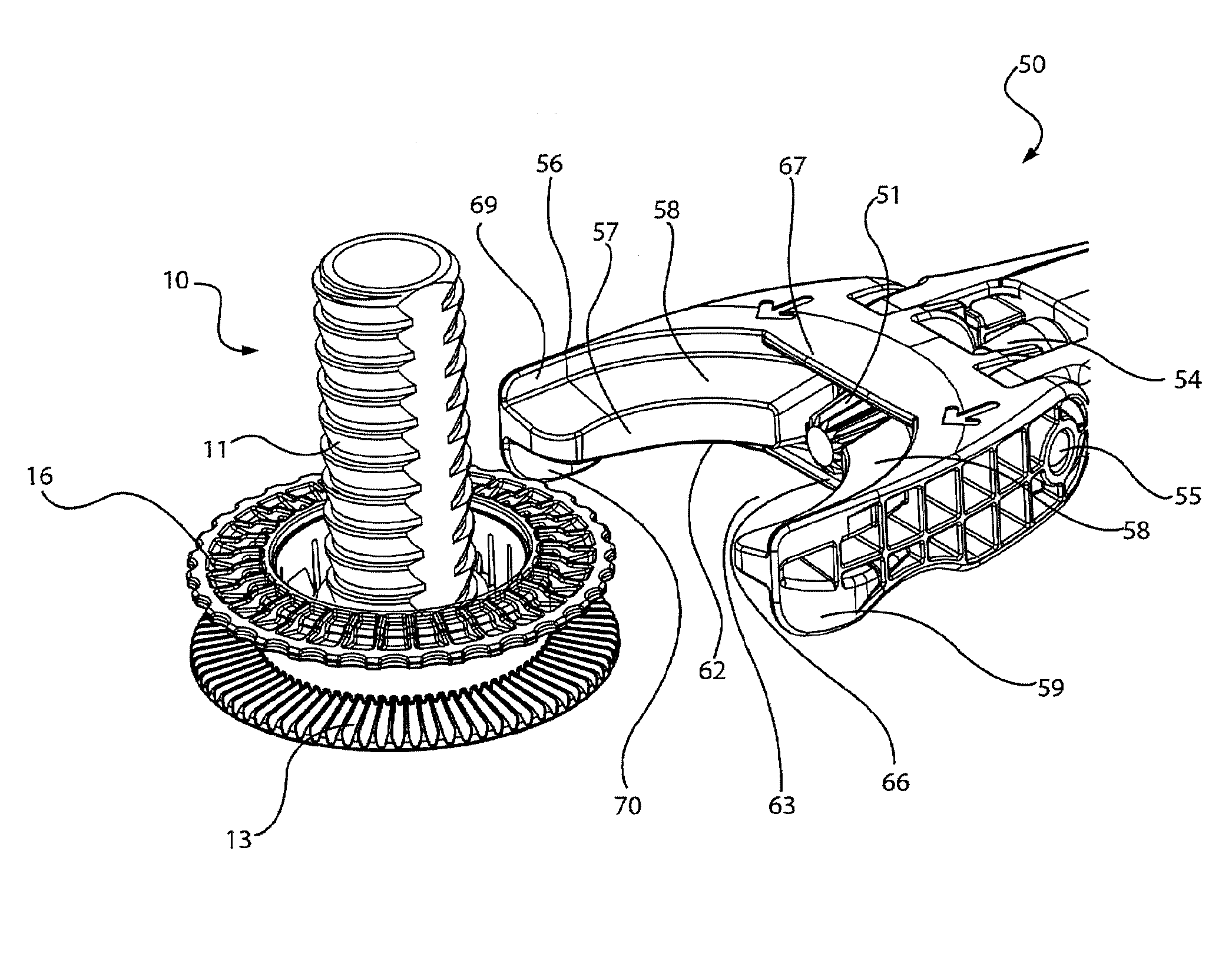
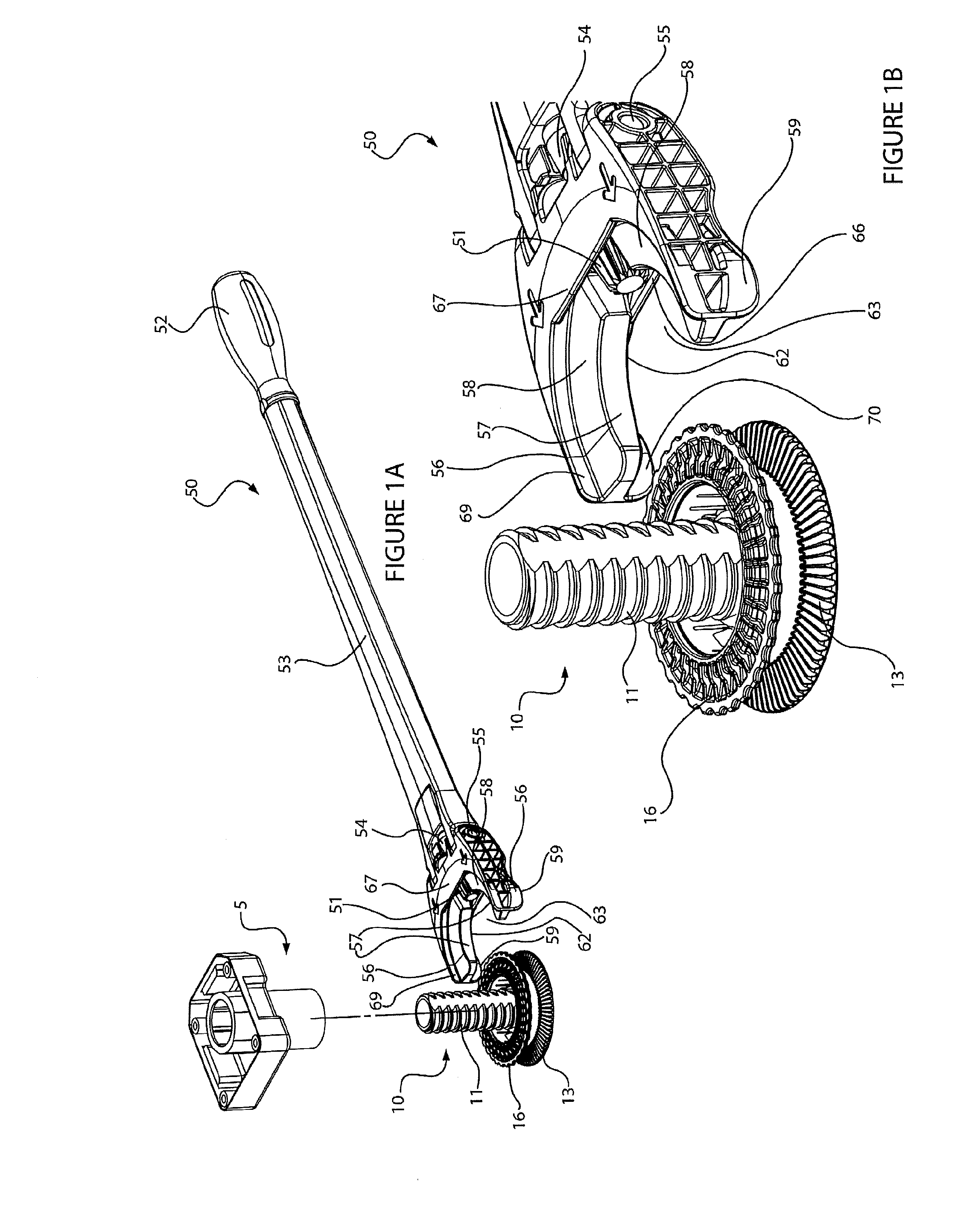
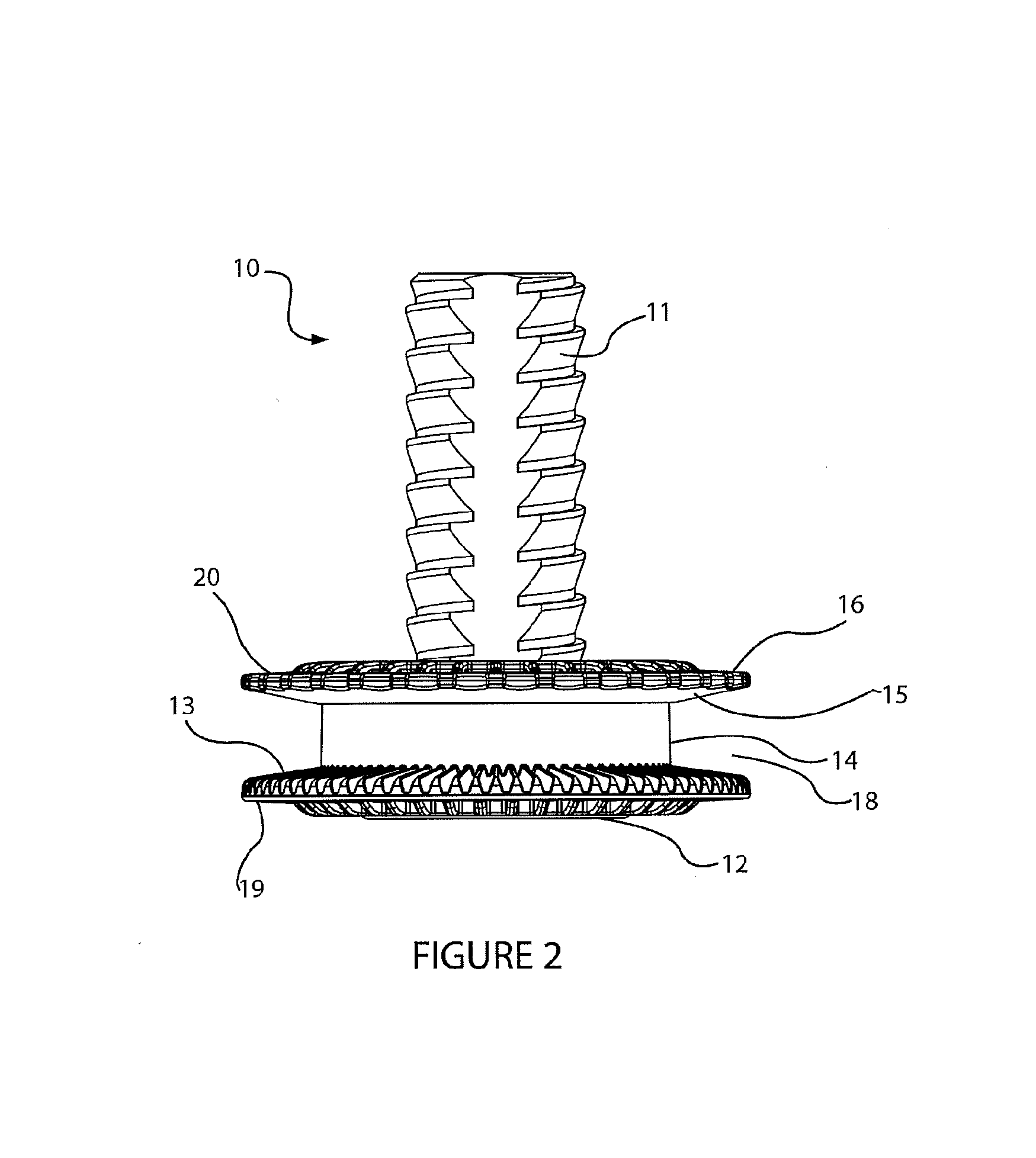
[0213]Various embodiments of a foot and / or a tool for adjusting the foot are described with reference to the Figures. The same reference numerals are used throughout to designate the same or similar components in various embodiments described.

[0214]FIGS. 1A to 10 illustrate a height adjustable foot or prop and a tool for adjusting the foot or prop according to some embodiments of the present invention. The foot or prop is referred to herein as a foot for height adjustment of a cabinet, appliance or structure or other object. A person skilled in the art will understand the foot or prop could also be used for sideways support of an object, for example supporting a cabinet from a vertical wall. In some embodiments the foot 10 comprises a threaded shaft 11. In use the threaded shaft is received in a threaded socket 5 or component (for example a nut) fixed to a cabinet, appliance or structure (herein an object) or other object to be height adjusted or leveled. The foot and threaded socke...


PUM


Abstract

An apparatus for adjusting a height adjustable leg for supporting a cabinet, appliance or structure is described. The apparatus includes a coupling (10) comprising a driven member or feature (13). The coupling forms part of a height adjustable leg. The apparatus also includes a tool (50) comprising a driving member (51) and a torque input (52) for applying torque to the driving member. The tool and the coupling are complementarily adapted to releasably maintain engagement between the driving member and the driven member or feature to allow the driving member to drive the driven member or feature to rotate the coupling about a longitudinal axis of the leg for height adjustment of the leg. The driving member and the driven member are gears that releasably mesh together when the tool is engaged with the coupling.

Description

FIELD OF THE INVENTION[0001]The present invention relates to an apparatus for adjusting a height adjustable leg for leveling or adjusting the height of cabinetry such as kitchen, bathroom or laundry cabinetry, or an appliance, or any other object that requires height or leveling adjustment. The present invention also relates to a coupling for forming part of a height adjustable leg, and a tool for adjusting the height of a height adjustable leg via such a coupling.BACKGROUND TO THE INVENTION[0002]Height adjustable legs that are used to support cabinets, appliances, furniture or the like are known. They typically comprise a vertically extending threaded shaft received in a corresponding threaded socket fixed to an appliance or cabinet to be height adjusted or levelled. The socket is fixed to the object, so that rotation of the shaft causes a foot of the leg to move axially relative to the socket to set the height of the object supported by the foot. To rotate or turn the threaded sha...

Claims


Application Information

Patent Timeline
Patent Type & Authority Applications(United States)
IPC IPC(8): A47B91/02B25B13/46B25B23/00F16M11/24
CPCA47B91/02A47L15/4253D06F39/125F16M7/00F16M2200/08B25B13/46B25B23/0028F16M11/24A47B91/024F16M2200/04
Inventor DE BRUIN, WIM JAN
Owner DESIGNERSCOPE LTD
Why Eureka
Try Eureka