Computed tomography system having cooling system

a computed tomography and cooling system technology, applied in the field of computed tomography systems, can solve problems such as the reduction of the durability of the ct system

Active Publication Date: 2016-08-18
SAMSUNG ELECTRONICS CO LTD
View PDF3 Cites 9 Cited by
  • Summary
  • Abstract
  • Description
  • Claims
  • Application Information

AI Technical Summary

Benefits of technology

[0009]According to an aspect of the present disclosure, in a cooling system of a CT system, the cooling system includes a gantry and a table that moves an object into a bore of the gantry, w

Problems solved by technology

The fans for respective parts and an exhaust fan of the gantry of the CT system may be source

Method used


Image

  • Computed tomography system having cooling system
  • Computed tomography system having cooling system
  • Computed tomography system having cooling system

Examples


Embodiment Construction

[0032]A cooling system of a computed tomography (CT) system will now be described in detail with reference to certain embodiments, examples of which are illustrated in the accompanying drawings. An artisan will understand and appreciate that the appended claims are not limited to the aspects of the disclosure shown in the drawings. In the drawings, like reference numerals refer to like elements throughout and elements having the same numeral may be formed of the same material. Also, in the drawings, sizes of elements may be exaggerated for convenience and clarity of explanation.

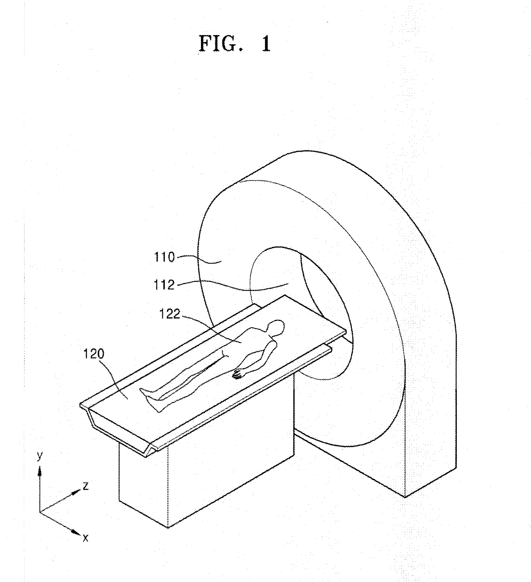
[0033]FIG. 1 is a schematic perspective view of a CT system 100 according to an embodiment of the disclosure.

[0034]Referring now to FIG. 1, the CT system 100 according to an embodiment may include a gantry 110 having a cylindrically shaped bore 112 in a center thereof and a table 120 that transports an object 122 (such as a patient) to be examined into and out of the bore 112 of the gantry 110. The object 122...


PUM


Abstract

A cooling system of a computed tomography (CT) system provides for a more efficient operation than known heretofore. The cooling system of the CT system includes a gantry and a table that moves an object into a bore of the gantry. The gantry includes part boxes mounted therein, and blade elements are formed in regions of the part boxes. The cooling system of the CT system includes a cooling method that includes a multiple cooling method including a stand-by mode and an operating mode.

Description

CLAIM OF PRIORITY[0001]This application claims the benefit of priority from Korean Patent Application No. 10-2015-0021774, filed on Feb. 12, 2015, in the Korean Intellectual Property Office, the disclosure of which is incorporated by reference herein in its entirety.BACKGROUND[0002]1. Field of the Disclosure[0003]The present disclosure relates to computed tomography (CT) systems that include a cooling system.[0004]2. Description of the Related Art[0005]With recent advances in medical technology, various methods of obtaining internal information of a living body have been developed. In particular, a tomography system is now widely used. With regard to tomography systems, a computed tomography (CT) system is now in widespread use. The CT system is a device for obtaining an image such that, after irradiating an X-ray toward an object from various angles, the X-ray that passes through the object is measured, and afterwards, the degree of absorption of the X-ray with respect to a cross-s...

Claims


Application Information

Patent Timeline
IPC IPC(8): A61B6/00A61B6/04A61B6/03
CPCA61B6/4488A61B6/0407A61B6/035A61B6/4291A61B2560/0406H01J2235/12H01J2235/1208H01J2235/1216H01J2235/1225H01J2235/127H01J2237/002H05G1/025
Inventor YUN, ALEXANDERKIM, SUNG-KINA, JEONG-MINSEONG, ILWON, CHANG-YEONCHO, TAE-SIK
Owner SAMSUNG ELECTRONICS CO LTD
Why Eureka
Try Eureka