Unlock instant, AI-driven research and patent intelligence for your innovation.

Workpiece positioning apparatus using imaging unit

Active Publication Date: 2016-08-18
FANUC CORP
View PDF2 Cites 10 Cited by
  • Summary
  • Abstract
  • Description
  • Claims
  • Application Information

AI Technical Summary

Benefits of technology

The purpose of this invention is to create a positioning system that can easily and quickly position a workpiece.

Problems solved by technology

Thus, when a burr or the like exists in the outer profile of the workpiece, for example, there is a possibility that an error detection may occur.
Further, when a feature point is printed on the workpiece, it is not possible to detect such a feature point.
Moreover, an overshoot occurs to detect the workpiece, and a lot of time is needed due to the extra moving distance.

Method used


Image

  • Workpiece positioning apparatus using imaging unit
  • Workpiece positioning apparatus using imaging unit
  • Workpiece positioning apparatus using imaging unit

Examples


Embodiment Construction

[0016]Embodiments of the present invention will be described with reference to the accompanying drawings hereinbelow. In the drawings, like members are denoted by like reference numerals. In order to facilitate understanding, the scale of the drawings is changed arbitrarily.

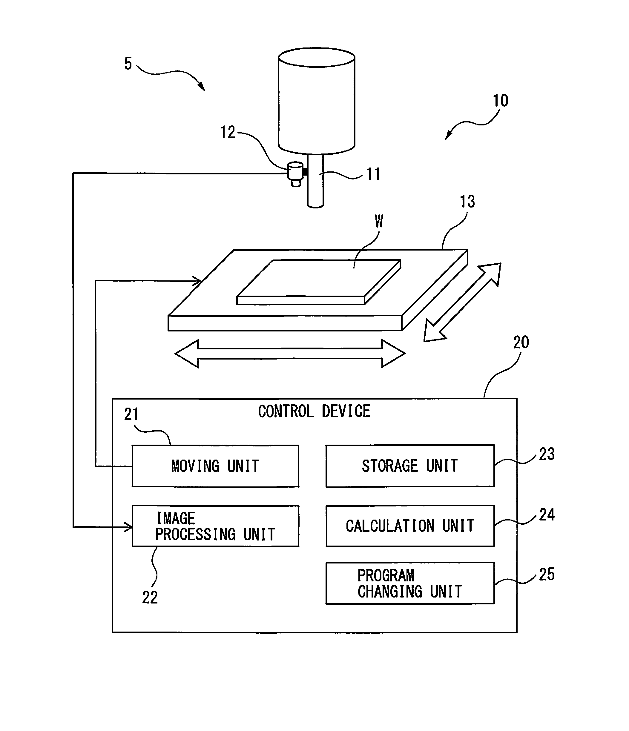
[0017]FIG. 1 is a schematic view of a positioning apparatus based on the present invention. As illustrated in FIG. 1, a tool (not shown) mounted on a spindle 11 of a machine tool 5 is configured to machine a workpiece W fixed on a table 13. The spindle 11 of the machine tool 5 is capable of reciprocation in a vertical direction (e.g., Z direction) as well as rotation. The positioning apparatus 10 of the present invention mainly includes the machine tool 5, and a control device 20 that controls the machine tool 5.

[0018]As illustrated in FIG. 1, an imaging unit 12, e.g., a camera is fixed to the spindle 11. Thus, the positional relationship between the imaging unit 12 and the spindle 11 is fixed. Preferably, the op...


PUM


Abstract

A positioning apparatus includes: a calculation unit that calculates an amount of deviation between a position of a feature point of a reference workpiece and a feature point of a workpiece by comparing a relative position of an imaging unit with respect to a table when the workpiece is imaged by the imaging unit with a reference relative position, and comparing a position of a feature point of the workpiece in the image of the workpiece imaged by the imaging unit with a reference point image position; and a program changing unit that generates a correction amount such that the amount of deviation calculated by the calculation unit becomes zero, and thereby changes a program of the machine tool.

Description

BACKGROUND OF THE INVENTION[0001]1. Field of the Invention[0002]The present invention relates to a workpiece positioning apparatus for a machine tool using an imaging unit such, for example, as vision sensor.[0003]2. Description of the Related Art[0004]In some cases, a workpiece is formed with two feature points for example, such as holes, bosses, notches or the like for positioning or phase-matching. Such feature points are engaged with a pin, spigot joint, or butt provided on the table of the machine tool to achieve positioning and phase-matching of the workpiece. In Japanese Examined Patent Publication No. 07-004737, a reference hole is formed in a workpiece as a feature point. An imaging unit, e.g., a camera images the reference hole of the workpiece through a hole formed through a table.[0005]In order to achieve more accurate positioning or the like, a touch probe is used which is mounted on a spindle of a machine tool. Preferably, the workpiece is positioned and phase-matched ...

Claims


Application Information

Patent Timeline
IPC IPC(8): G06T7/00G06K9/62H04N7/18
CPCG06T7/001H04N7/18G06T2207/30164G06K9/6201G06T7/0044B23Q17/22B23Q15/22G05B19/402G05B2219/49113G06V10/752B21D43/003G01B11/002G06T7/564G06T7/74
Inventor OGAWA, KENICHI
Owner FANUC CORP
Features
  • R&D
  • Intellectual Property
  • Life Sciences
  • Materials
  • Tech Scout
  • Unparalleled Data Quality
  • Higher Quality Content
  • 60% Fewer Hallucinations
Learn More