Compound engine assembly with mount cage
a technology of compound engine and mount cage, which is applied in the direction of piston power plants, jet propulsion plants, mechanical equipment, etc., can solve the problems of difficult to adapt them to aircraft applications
- Summary
- Abstract
- Description
- Claims
- Application Information
AI Technical Summary
Benefits of technology
Problems solved by technology
Method used
Image
Examples
Embodiment Construction
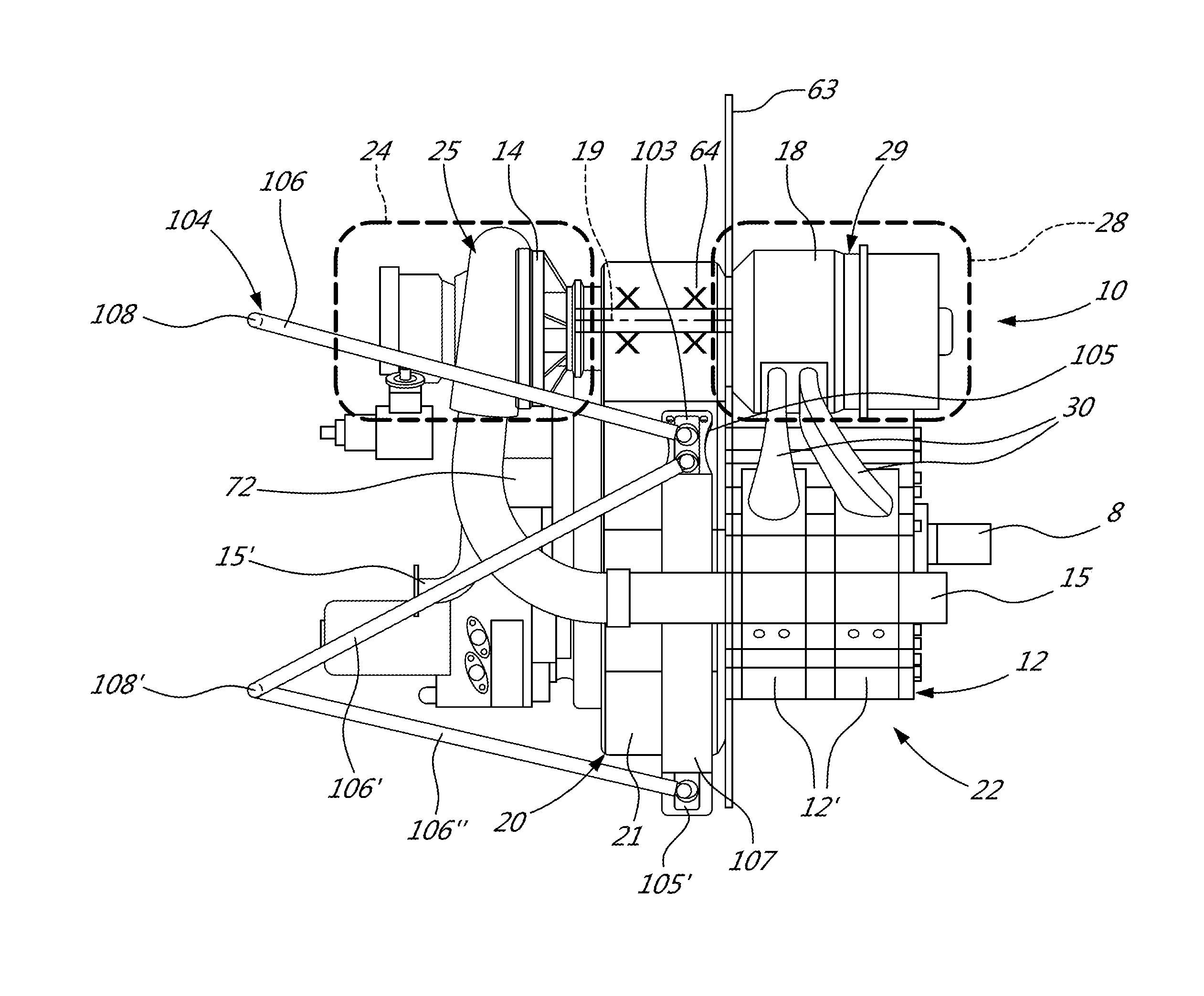
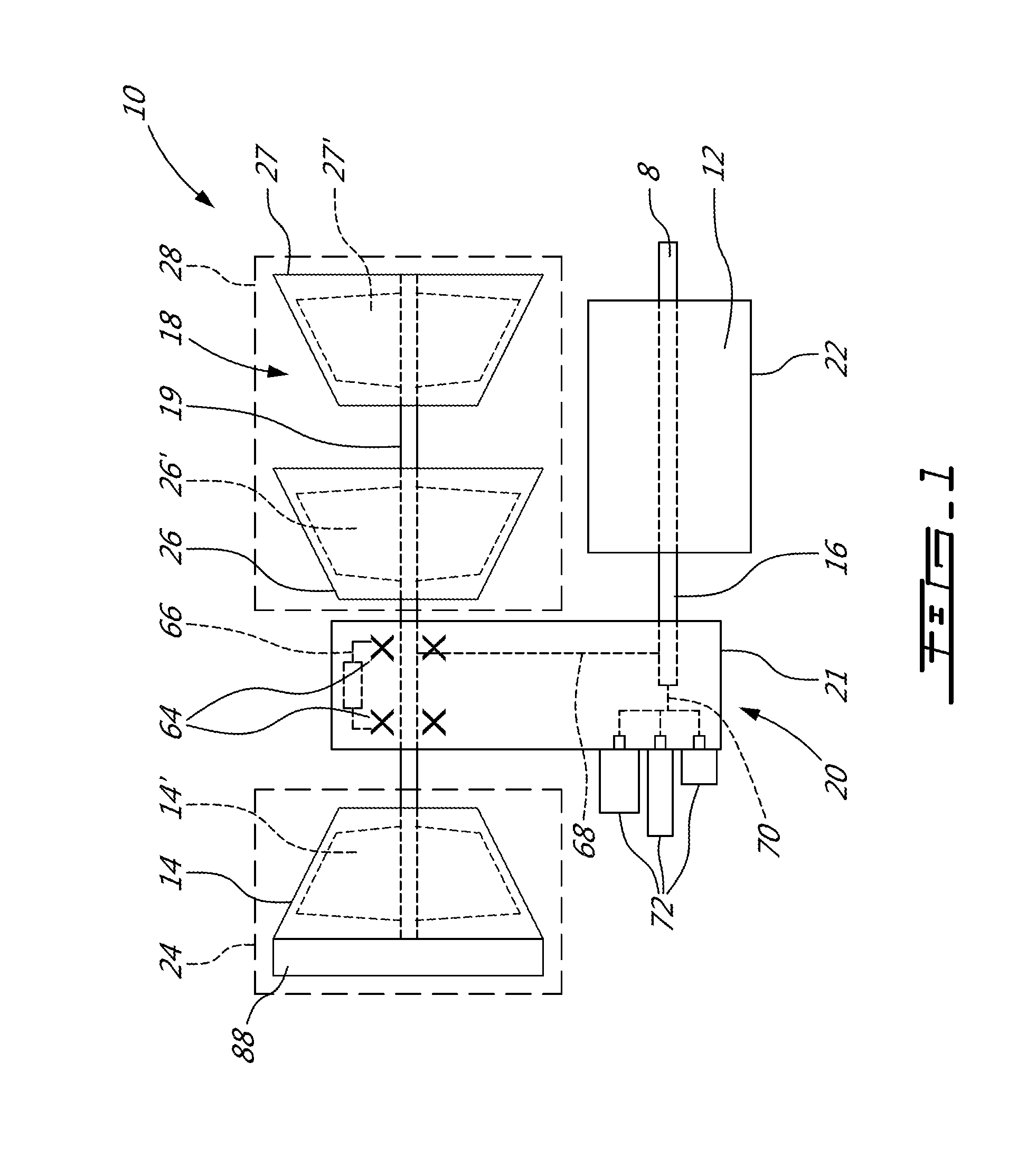
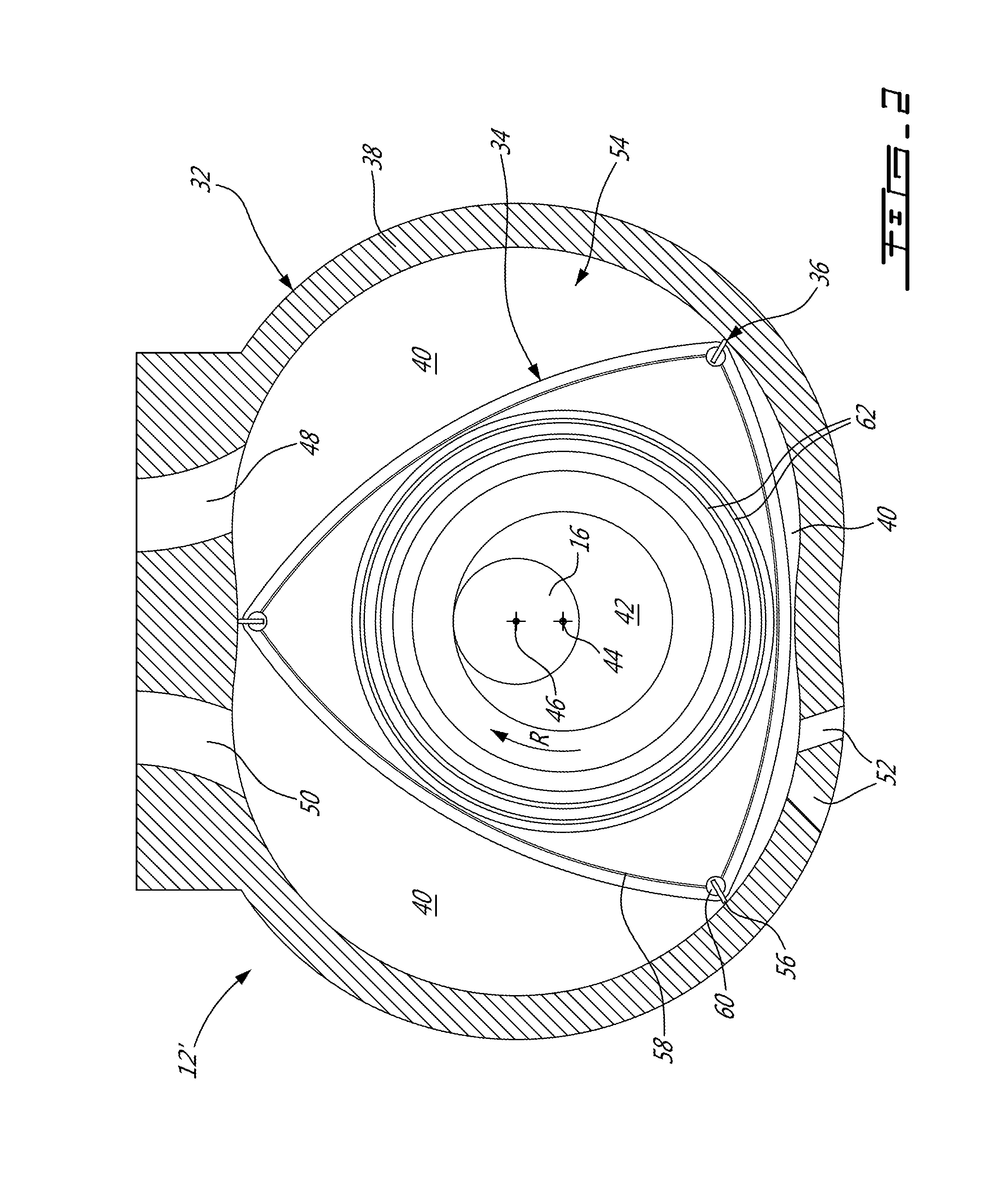
[0020]Referring to FIG. 1, a compound engine assembly 10 is generally shown, including a liquid cooled heavy fueled multi-rotor rotary engine core 12. The engine core 12 has an engine shaft 16 driven by the engine core 12 and driving a rotatable load, which is shown here as a drive shaft 8. The drive shaft 8 may be an integral part of the engine shaft 16, be directly connected thereto, or be connected thereto through a gearbox (not shown). It is understood that the compound engine assembly 10 may alternately be configured to drive any other appropriate type of load, including, but not limited to, one or more generator(s), propeller(s), accessory(ies), rotor mast(s), compressor(s), or any other appropriate type of load or combination thereof.
[0021]The compound engine assembly 10 is configured as a single shaft engine. The term “single shaft” is intended herein to describe a compound engine where all the rotating components (compressor rotor(s), turbine rotor(s), engine shaft, accesso...
PUM
 Abstract
Description
Claims
Application Information
 - R&D
- Intellectual Property
- Life Sciences
- Materials
- Tech Scout
- Unparalleled Data Quality
- Higher Quality Content
- 60% Fewer Hallucinations
Browse by: Latest US Patents, China's latest patents, Technical Efficacy Thesaurus, Application Domain, Technology Topic, Popular Technical Reports.
© 2025 PatSnap. All rights reserved.Legal|Privacy policy|Modern Slavery Act Transparency Statement|Sitemap|About US| Contact US: help@patsnap.com


