Image forming apparatus

a technology of image forming apparatus and developer roller, which is applied in the direction of electrographic process apparatus, instruments, optics, etc., can solve the problems of affecting the quality of image forming, the rotation speed of the developer roller and the neighboring parts that contact the developer roller may also increase, and the friction between the developer roller and neighboring parts that contact the developer roller may increase. , the effect of speeding up the speed of image forming

Active Publication Date: 2016-08-25
BROTHER KOGYO KK
View PDF4 Cites 9 Cited by
  • Summary
  • Abstract
  • Description
  • Claims
  • Application Information

AI Technical Summary

Benefits of technology

[0006]When a speed to form an image in an image forming apparatus increases, a rotation speed for a developer roller in the processing cartridge may also increase, and friction between the developer roller and neighboring parts that contact the developer roller may increase. In this regard, an amount of heat generated in a developer agent container and the developer roller may also increase. When a developer agent, e.g., toner, in the developer agent container is exposed to the heat, the toner may be undesirably softened, and the softened toner may affect an image forming quality.
[0007]The present disclosure is advantageous in that an image forming apparatus, in which an area underneath a processing cartridge may be efficiently cooled, is provided.

Problems solved by technology

When a speed to form an image in an image forming apparatus increases, a rotation speed for a developer roller in the processing cartridge may also increase, and friction between the developer roller and neighboring parts that contact the developer roller may increase.
When a developer agent, e.g., toner, in the developer agent container is exposed to the heat, the toner may be undesirably softened, and the softened toner may affect an image forming quality.

Method used


Image

  • Image forming apparatus
  • Image forming apparatus
  • Image forming apparatus

Examples


Embodiment Construction

[0016]Hereinafter, an image forming apparatus 1 according to an embodiment of the present disclosure will be described with reference to the accompanying drawings. It is noted that various connections may be set forth between elements in the following description. These connections in general, and unless specified otherwise, may be direct or indirect, and this specification is not intended to be limiting in this respect.

[0017]In the following description, identical parts or items may be referred to by a same reference sign, and redundant explanation of those will be omitted. A quantity of each element, part, or item is, unless specified otherwise, at least one. The present embodiment may not necessarily be limited to the embodiment described below.

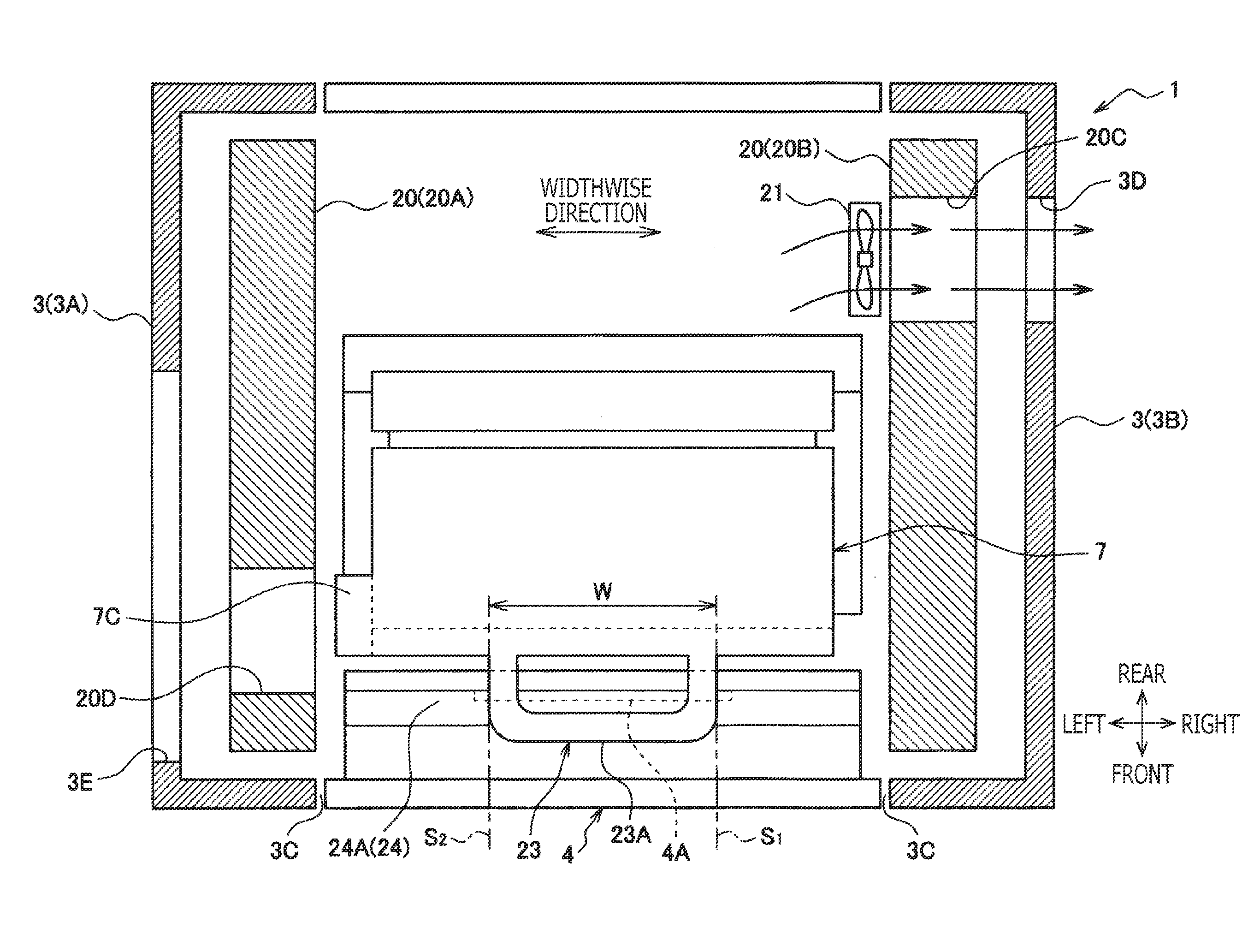
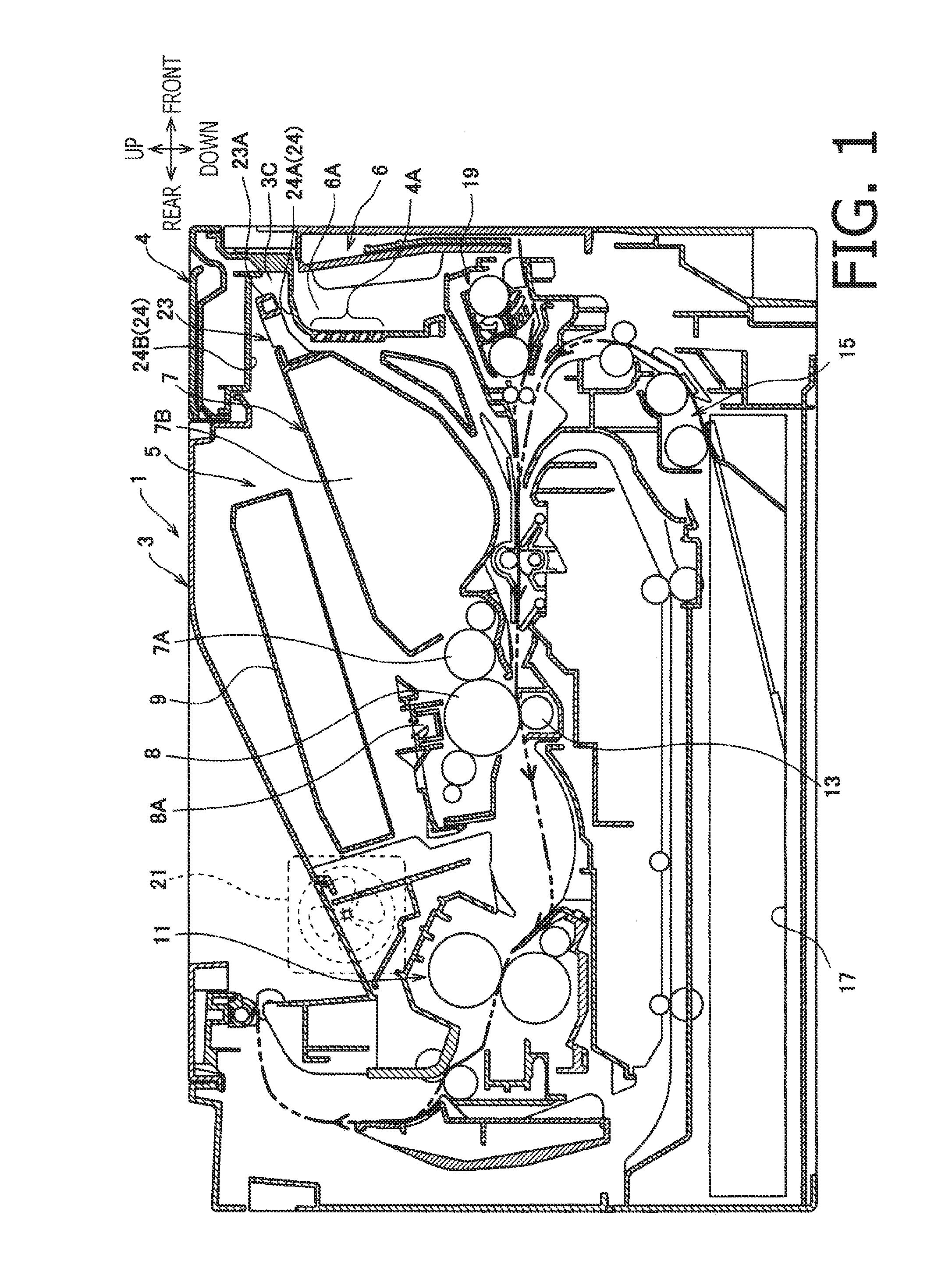
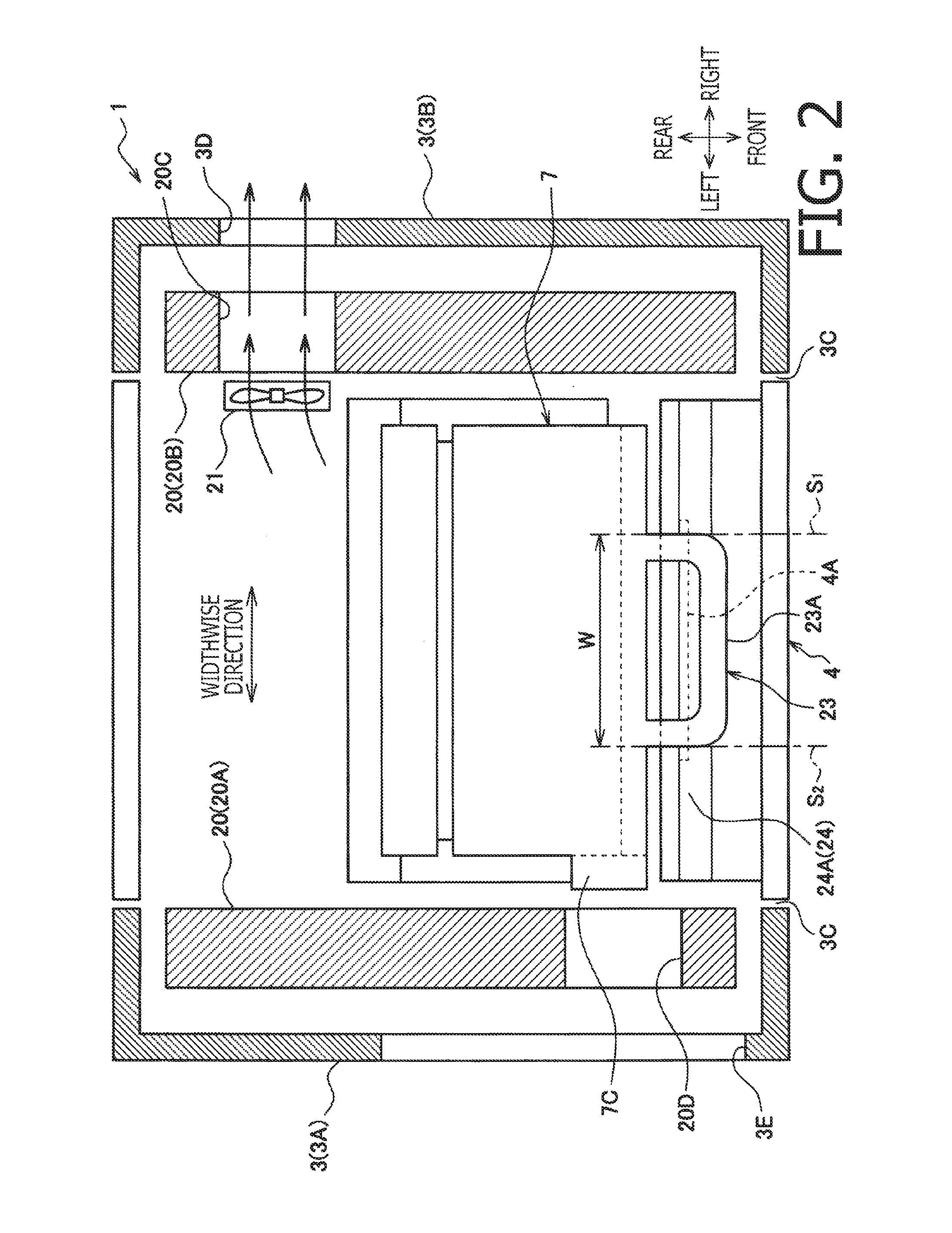
[0018]1. Overall Configuration of the Image Forming Apparatus

[0019]The image forming apparatus 1 may be a monochrome printing apparatus. In the following description, directions concerning the image forming apparatus 1 and each part or ite...


PUM


Abstract

An image forming apparatus to form an image electro-photographically is provided. The image forming apparatus includes a housing formed to have an opening; a cover being movable between an open position and an exposing position and having a ventilation port, through which air is allowed to flow; a cartridge having a developer roller and being detachably attached to a body of the image forming apparatus through the opening; a discharging fan arranged on an opposite side from the opening across the cartridge; a handle arranged on the cartridge to extend from the cartridge in a direction toward the opening in an upper position with respect to the ventilation port, when the cartridge is attached to the body and the opening is covered by the cover; and a facing part arranged on the cover to face the handle in a vertically displaced position with respect to the handle.

Description

CROSS REFERENCE TO RELATED APPLICATION[0001]This application claims priority from Japanese Patent Application No. 2015-033141, filed on Feb. 23, 2015, the entire subject matters of which are incorporated herein by reference.BACKGROUND[0002]1. Technical Field[0003]An aspect of the present disclosure relates to an image forming apparatus capable of forming an image electro-photographically on a sheet.[0004]2. Related Art[0005]An image forming apparatus having a ventilation path to draw cooling air inside is known. The ventilation path may be formed in a guide member, which guides a sheet being conveyed, to draw the cooling air underneath a processing cartridge.SUMMARY[0006]When a speed to form an image in an image forming apparatus increases, a rotation speed for a developer roller in the processing cartridge may also increase, and friction between the developer roller and neighboring parts that contact the developer roller may increase. In this regard, an amount of heat generated in ...

Claims


Application Information

Patent Timeline
Patent Type & Authority Applications(United States)
IPC IPC(8): G03G21/20G03G15/04
CPCG03G21/1676G03G21/206G03G21/1623
Inventor MINOSHIMA, SAYA
Owner BROTHER KOGYO KK
Why Eureka
Try Eureka