

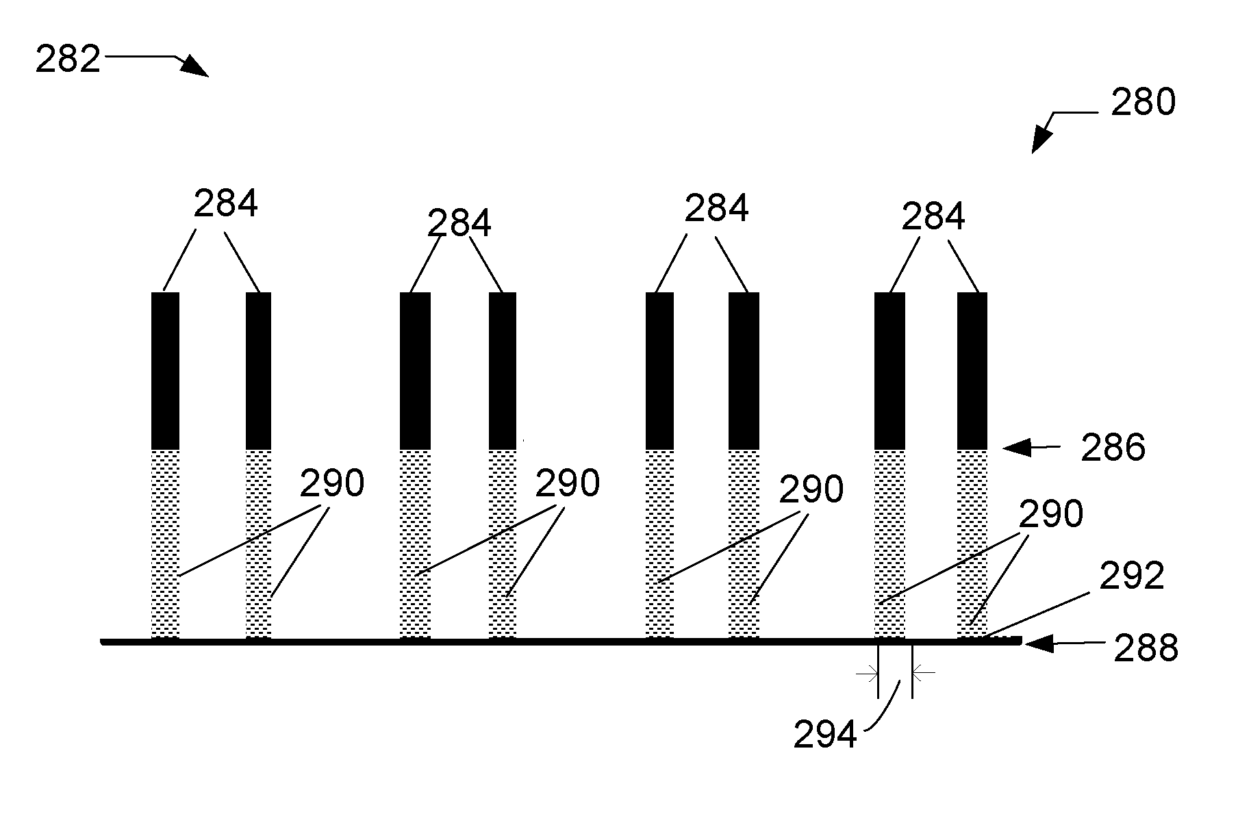
Material processing to achieve sub-10nm patterning
a material processing and sub-10nm technology, applied in the direction of electrical equipment, basic electric elements, electric discharge tubes, etc., can solve the problems of inconvenient methods and spatial limitations inherent in the conventional dp technique, and achieve the effect of increasing the pattern density of the structur
- Summary
- Abstract
- Description
- Claims
- Application Information
AI Technical Summary
Benefits of technology
Problems solved by technology
Method used
Image

Examples
Embodiment Construction
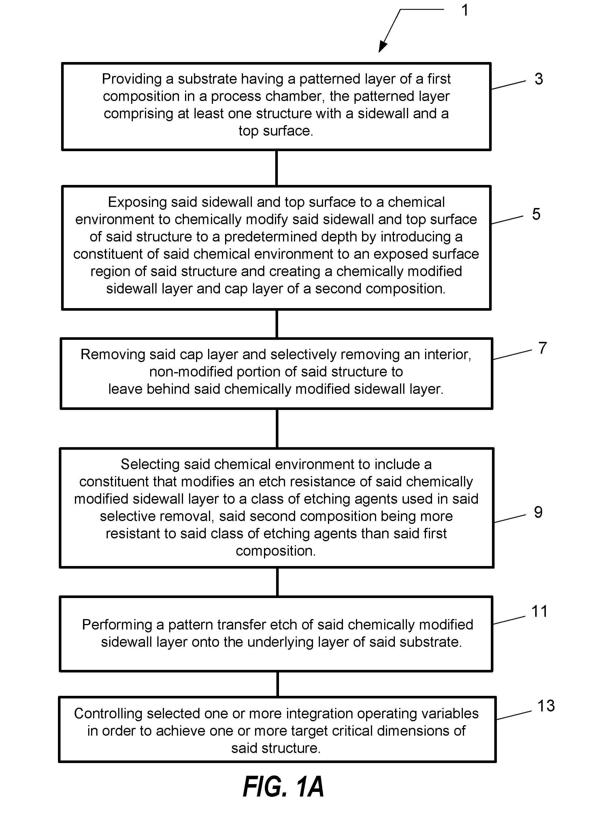
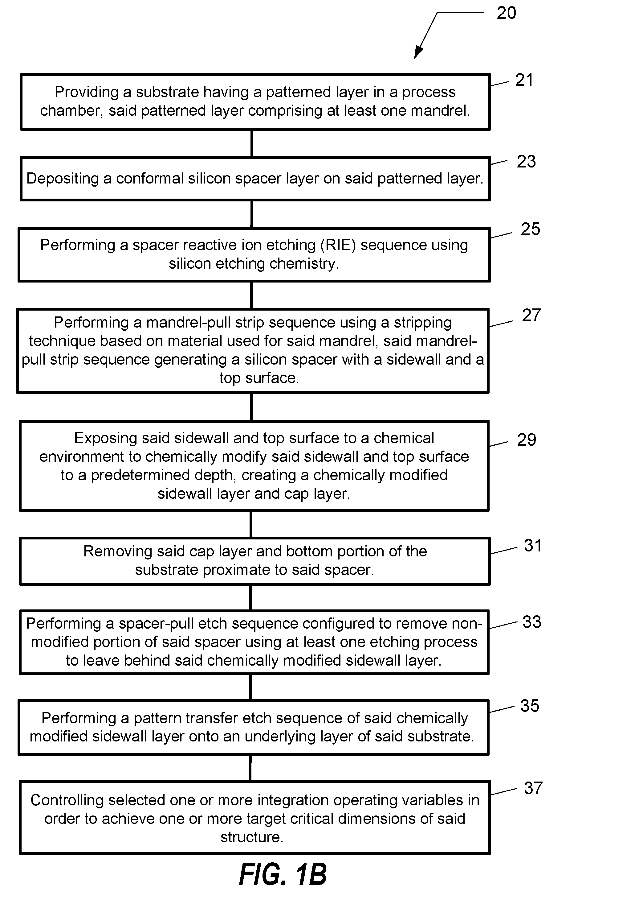
[0040]In the following description, for purposes of explanation and not limitation, specific details are set forth, such as a particular geometry of a processing system, descriptions of various components and processes used therein. However, it should be understood that the invention may be practiced in other embodiments that depart from these specific details.
[0041]Similarly, for purposes of explanation, specific numbers, materials, and configurations are set forth in order to provide a thorough understanding of the invention. Nevertheless, the invention may be practiced without specific details. Furthermore, it is understood that the various embodiments shown in the figures are illustrative representations and are not necessarily drawn to scale.
[0042]Various operations will be described as multiple discrete operations in turn, in a manner that is most helpful in understanding the invention. However, the order of description should not be construed as to imply that these operations...
PUM
 Abstract
Description
Claims
Application Information