Modular power plant assembly

a power plant and module technology, applied in the direction of substation/switching arrangement details, substation/switching arrangement boards/panels/desks, distribution substations, etc., can solve the problems of high transportation cost, inability to provide a dedicated electrical network, and limited electricity

Inactive Publication Date: 2016-08-25
SOLAR TURBINES
View PDF19 Cites 141 Cited by
  • Summary
  • Abstract
  • Description
  • Claims
  • Application Information

AI Technical Summary

Benefits of technology

[0005]In an aspect of the present disclosure, a modular power plant assembly for distributed power generation is provided. The power plant assembly includes a power generator assembly for generating electrical power mounted on a trailer An Alternating Current / Direct Current (AC / DC) distribution panel is electrically coupled to the power generator assembly. The AC / DC distribution panel is mounted on the power generator assembly. The power plant assembly further includes a Medium Voltage module electrically coupled to the power generator assembly. The Medium Voltage module is mounted on the trailer. The AC / DC distribution panel and the Medium Voltage module together control and distribute the electrical power generated by the power generator assembly. A plurality of auxiliary components for supplying fuel and air to the power generator assembly are mounted adjacent to the power generator assembly on a skid attached to an upper deck of the trailer.

Problems solved by technology

Generally, in remote locations and / or developing regions, such as rural areas, oil and gas installations, research stations, dam installations, and so on, utilities such as electricity may be limited or non-existent.
In such regions, providing a dedicated electrical network may not be feasible and cost efficient mainly due to remoteness of such regions to the nearest power generation facility or power grid, level of demand, and / or demand inconsistency.
Due to the number and complexity of these modules, the modular power plants may require high transportation cost, high installation cost, high installation time, and significant installation expertise.
Also, such modular power plants may not be scalable for supporting future capacity expansion.

Method used


Image

  • Modular power plant assembly
  • Modular power plant assembly
  • Modular power plant assembly

Examples


Embodiment Construction

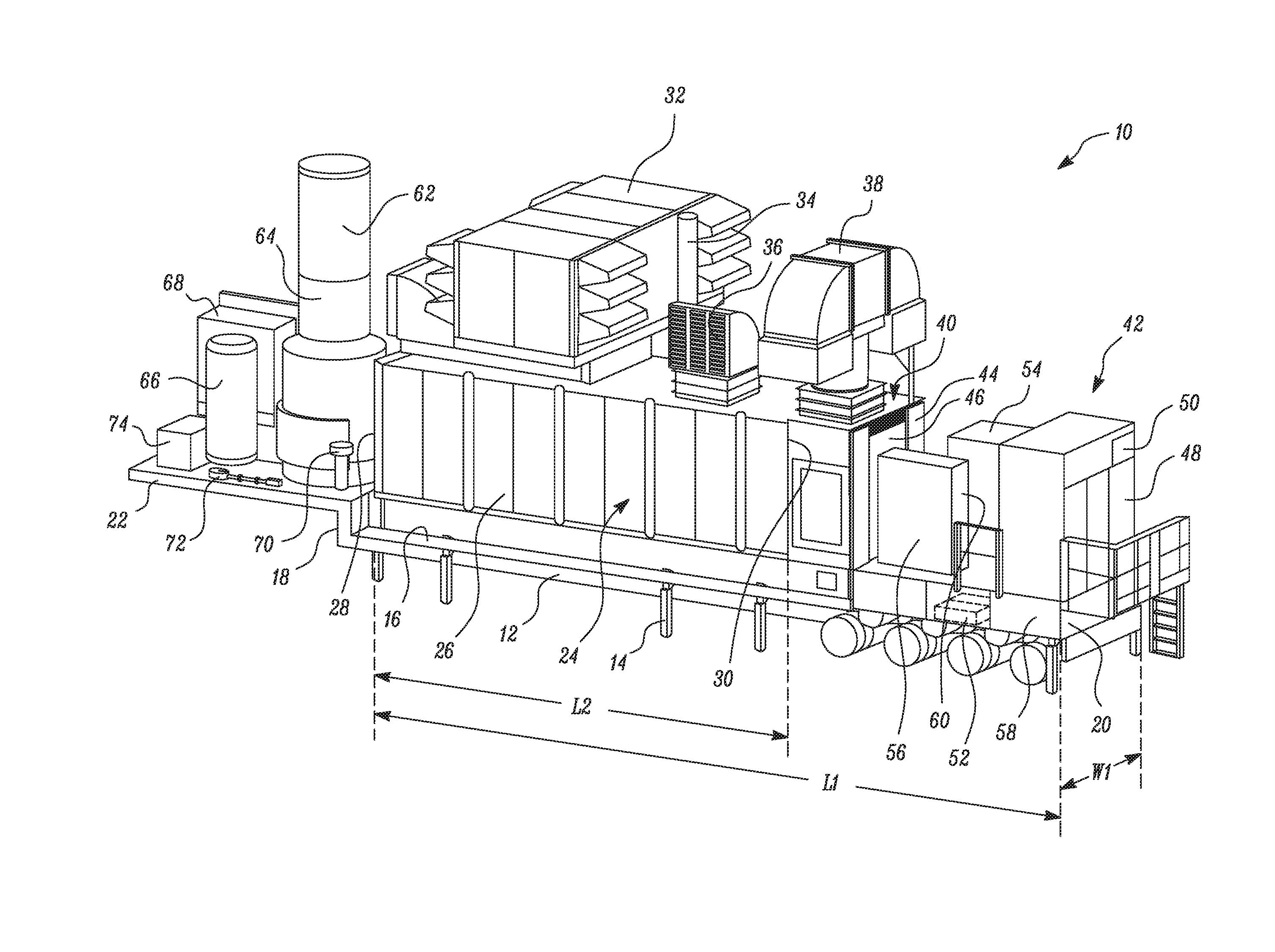
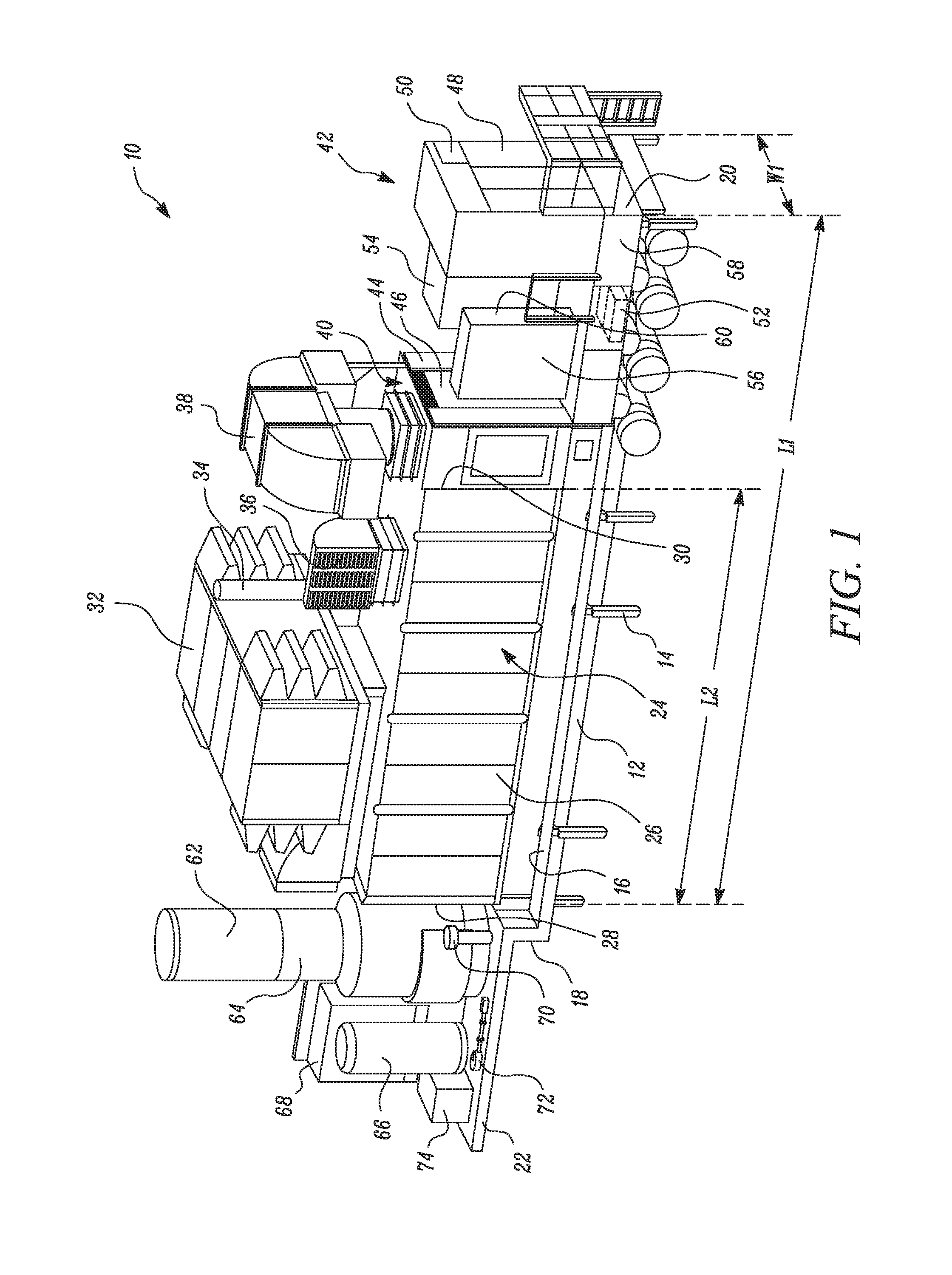
[0010]Wherever possible, the same reference numbers will be used throughout the drawings to refer to same or like parts. Referring to FIG. 1, a Mobile Power Unit (MPU) 10 is shown. The MPU 10 includes various modules and subsystems arranged on a trailer 12. The trailer 12 may have multiple axles having wheels mounted on them. For example, the trailer 12 may have four axles. The trailer 12 includes multiple supporting legs 14 for supporting the trailer 12 while parked in a stationary condition on the ground, The trailer 12 further includes a trailer floor 16 on which the various modules and subsystems are mounted. The trailer 12 may include isolating pads (not shown) mounted on the trailer floor 16. The isolating pads may absorb the vibrations produced by the operation of various modules and subsystems mounted on the trailer floor 16. The trailer floor 16 has a first end 18 and a second end 20. As shown in the FIG. 1, a skid 22 is attached to the first end 18 of the trailer floor 16....


PUM


Abstract

A modular power plant assembly for distributed power generation includes a power generator assembly, to generate electrical power, mounted on a trailer. An AC/DC distribution panel electrically coupled to the power generator assembly is mounted on the power generator assembly. A Medium Voltage module electrically coupled to the power generator assembly is mounted on the trailer. The AC/DC distribution panel and the Medium Voltage module together control and distribute the electrical power generated by the power generator assembly. A plurality of auxiliary components to supply fuel and air to the power generator assembly are mounted adjacent to the power generator assembly on a skid attached to the trailer.

Description

TECHNICAL FIELD[0001]The present disclosure relates to a modular power plant assembly. More specifically, the present disclosure relates to a modular power plant assembly for distributed power generation.BACKGROUND[0002]Generally, in remote locations and / or developing regions, such as rural areas, oil and gas installations, research stations, dam installations, and so on, utilities such as electricity may be limited or non-existent. In such regions, providing a dedicated electrical network may not be feasible and cost efficient mainly due to remoteness of such regions to the nearest power generation facility or power grid, level of demand, and / or demand inconsistency. In such situations, modular power plants are generally used to meet the limited and / or varying demand of electricity of such regions. The modular power plants are readily transportable and may be installed at any location based on the demand.[0003]U.S. Pat. No. 8,816,518 describes a containerized electrical substation ...

Claims


Application Information

Patent Timeline
Patent Type & Authority Applications(United States)
IPC IPC(8): H02B1/04F01D15/10
CPCF01D15/10H02B1/04F01D25/285F05D2220/76F05D2260/02H02B1/52H02B7/06
Inventor TAWY, DALIA ELSTIMUS, ANTHONY R.THOMPSON, STEFFENRANGE, SCOTTHICKLE, JAMES R.SAMPATHKUMAR, VARADHARAJANCAFARO, SILVIOLONGHI, FABRIZIOGIARDA, ROBERTOSORCE, GERLANDO
Owner SOLAR TURBINES
Why Eureka
Try Eureka