Inter-Node Interference Reduction Method, Node and System

a technology of node and interference reduction, applied in the field of internal node interference reduction technologies, to achieve the effect of small interferen

Inactive Publication Date: 2016-08-25
ZTE CORP
View PDF2 Cites 43 Cited by
  • Summary
  • Abstract
  • Description
  • Claims
  • Application Information

AI Technical Summary

Benefits of technology

[0065]The abovementioned technical solution obtains joint information of the interference of a neighboring node with a terminal of the present node from the link state information coming from the terminal, through the interference information interaction between the present node and the neighboring node, the neighboring node learns reasons of the interference, and then further schedules a terminal which would generate relatively sm

Problems solved by technology

When the UE executes the channel quality measurement in a connected state, if the interference level is high, its physic

Method used


Image

  • Inter-Node Interference Reduction Method, Node and System
  • Inter-Node Interference Reduction Method, Node and System
  • Inter-Node Interference Reduction Method, Node and System

Examples


application example 1

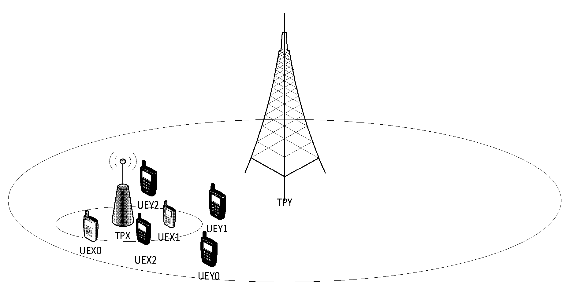
[0102]this application scenario comprises two nodes TPX and TPY, there are three UEs, respectively UEX0, UEX1 and UEX2, under the TPX coverage, and there are three UEs, respectively UEY1, UEY1 and UEY2, under the TPY coverage.

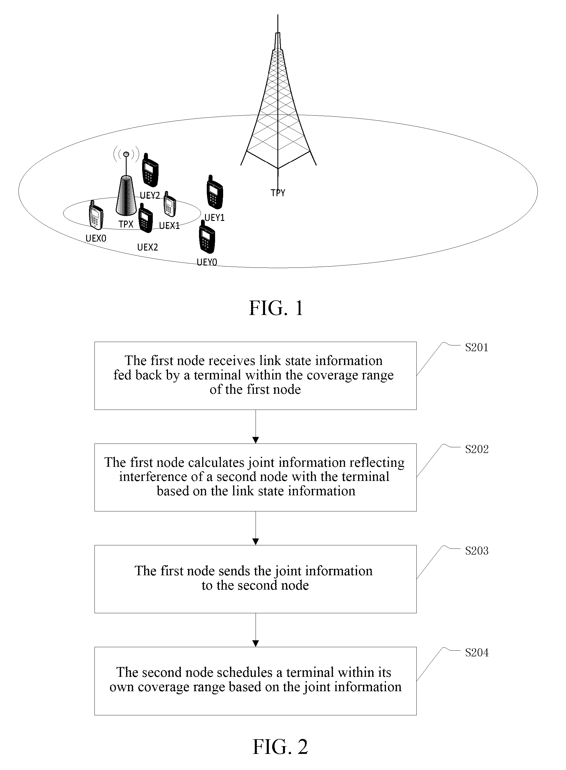
[0103]In STEP1, the TPX measures or receives the link state information from the TPX to the UEXn and fed back by the UEXn (n=0, 1, 2);

[0104]in STEP2, the TPX calculates the interference codeword and the power level limit value corresponding to the codeword coming from the TPY based on the principle of minimizing interference; a plurality of interference codewords constitute a codebook limit cluster, a plurality of power level limit values constitute a power level limit cluster, and the codebook limit cluster and the power level limit cluster constitute the joint information;

[0105]in STEP3, the TPX sends the joint information to the TPY through the interface of the TPX and the TPY;

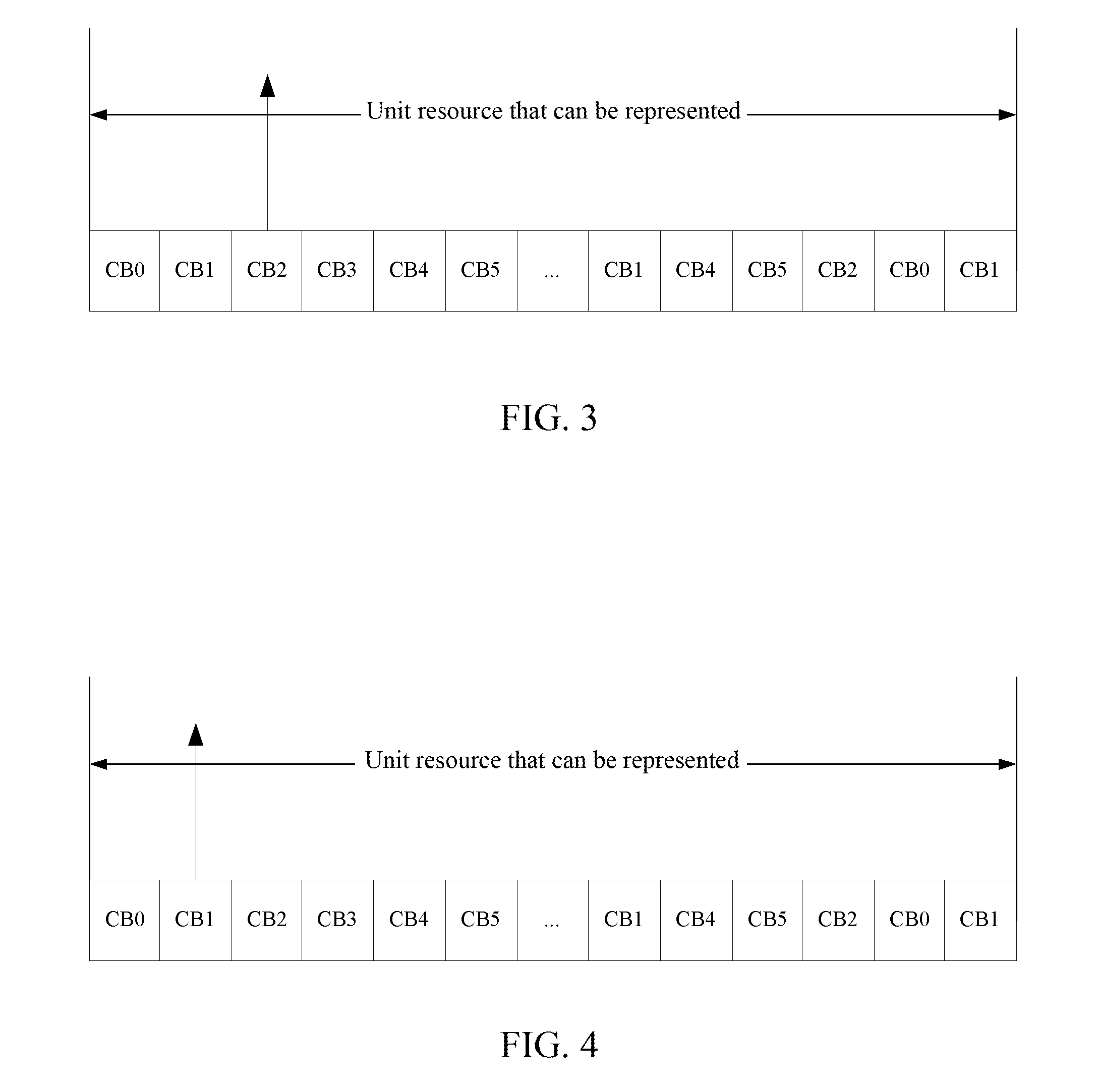
[0106]in STEP4, assuming that in the basic unit resource CB2, the optimal codeword...

application example 2

[0110]The application scenario comprises two nodes TPX and TPY, there are three UEs, respectively UEX0, UEX1 and UEX2, under the TPX coverage, and there are three UEs, respectively UEY1, UEY1 and UEY2, under the TPY coverage.

[0111]In STEP1, the TPX measures or receives the link state information from the TPX to the UEXn and fed back by the UEXn (n=0, 1, 2);

[0112]in STEP2, the TPX calculates an interference codewords, and a power level limit value as well as the priority level indication information corresponding to the codeword coming from the TPY based on the principle of minimizing interference; a plurality of interference codewords constitute a codebook limit cluster, a plurality of power level limit values constitute a power level limit cluster, a plurality of pieces of priority indication information constitute a priority indication information cluster, and the codebook limit cluster, the power level limit cluster and the priority indication information cluster constitute the j...

application example 3

[0117]The application scenario comprises two nodes TPX and TPY, there are three UEs, respectively UEX0, UEX1 and UEX2, under the TPX coverage, and there are three UEs, respectively UEY1, UEY1 and UEY2, under the TPY coverage.

[0118]In STEP1, the TPX measures or receives the link state information from the TPX to the UEXn and fed back by the UEXn (n=0, 1, 2);

[0119]in STEP2, the TPX calculates the joint information consisting of the codebook limit cluster, the power level limit cluster and the priority indication information cluster coming from the TPY based on the principle of minimizing interference;

[0120]in STEP3, the TPX sends the joint information to the TPY through the interface of the TPX and the TPY;

[0121]in STEP4, assuming that in the basic unit resource CB2, the optimal codewords of the UEY1, the UEY1 and the UEY2 are respectively B4, B5 and B6. When the TPY schedules, the TPY learns through the joint information that in the basic unit resource CB2, the optimal codewords corr...


PUM


Abstract

An inter-node interference reduction method, node and system, wherein the method includes: a first node obtaining link state information fed back by a terminal within the coverage range of the first node; the first node calculating joint information reflecting the interference of a second node with the terminal based on the link state information, and sending the joint information to the second node; the second node scheduling a terminal within its own coverage range based on the joint information, wherein the joint information includes a codebook limit cluster and further includes one or more of a power level limit cluster, a priority indication information cluster and an interference level indication information cluster, and a correspondence exists between constituent elements of any piece(s) of information within the joint information and constituent elements of other information except the any piece(s) of information within the joint information

Description

CROSS-REFERENCE TO RELATED APPLICATION(S)[0001]This application is the U.S. National Phase application of PCT application number PCT / CN2014 / 078174 having a PCT filing date of May 22, 2014, which claims priority of Chinese patent application 201310467745.4 filed on Oct. 8, 2013, the disclosures of which are hereby incorporated by reference.TECHNICAL FIELD[0002]The present invention relates to inter-node interference reduction technologies, and more particularly, to an inter-node interference reduction method, node and system.BACKGROUND OF RELATED ART[0003]The R8 and R9 versions of the LTE design Common Reference Signal (CRS) to measure the quality of a channel and to demodulate received data symbols. The user equipment (UE) can execute a channel quality measurement via a CRS to decide which target cell to execute a cell reselection and the switch. When the UE executes the channel quality measurement in a connected state, if the interference level is high, its physical layer may also ...

Claims


Application Information

Patent Timeline
IPC IPC(8): H04L5/00H04J11/00
CPCH04J11/0023H04L5/0035H04W88/08H04J11/0053H04L5/0073H04W52/0216H04J11/005Y02D30/70H04W72/54
Inventor GUO, SENBAXU, JUNLI, YU NGOKSUN, YUNFENG
Owner ZTE CORP
Why Eureka
Try Eureka