Method for adaptively regulating intelligent antenna wave beam width

An adaptive adjustment and beam width technology, applied in antennas, diversity/multi-antenna systems, electrical components, etc., can solve the problems of smart antenna beams that cannot be aligned and call drops

Inactive Publication Date: 2006-11-22
POTEVIO INFORMATION TECH
View PDF0 Cites 25 Cited by
  • Summary
  • Abstract
  • Description
  • Claims
  • Application Information

AI Technical Summary

Problems solved by technology

In this case, if the UE moves at a high speed within 50 meters from the base station, the beam of the smart antenna will not be aligned with the UE, resulting in call drop

Method used


Image

  • Method for adaptively regulating intelligent antenna wave beam width
  • Method for adaptively regulating intelligent antenna wave beam width
  • Method for adaptively regulating intelligent antenna wave beam width

Examples


Embodiment Construction

[0040] In order to make the objectives, technical solutions, and advantages of the invention clearer, the invention will be further described in detail below with reference to the accompanying drawings and embodiments.

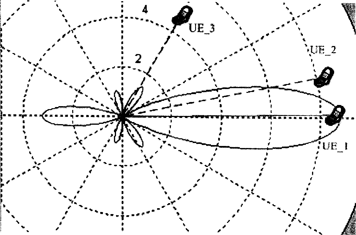
[0041] In order to solve the problem that the downlink beam cannot track the user when the UE moves at a large angular frequency, it is expected that the base station can adaptively adjust the downlink beam width of the smart antenna according to the UE relative to the base station's moving angular frequency ω. When the frequency ω is large, a downlink beam with a wider width is used to send data, and when the angular frequency ω of UE movement is small, a downlink beam with a narrow width is used to send data. Therefore, the method of the present invention mainly includes the following steps:

[0042] A. Set more than one downlink beam width for the smart antenna of the base station;

[0043] The multiple downlink beam widths set in this step can be determined ac...


PUM


Abstract

The invention discloses a self-adjusting method of intelligent antenna beam breadth, which comprises the following steps: A. setting at least one descending beam breadth for base station intelligent antenna; B. affirming moving angle frequency corresponding to base station for user equipment; C. selecting descending beam shape for the descending beam breadth to satisfy the descending beam breadth more than or equal the product of angle frequency and intelligent antenna beam direction adjusting time gap. The invention guarantees intelligent antenna beam to trace user equipment, when the angle frequency is large.

Description

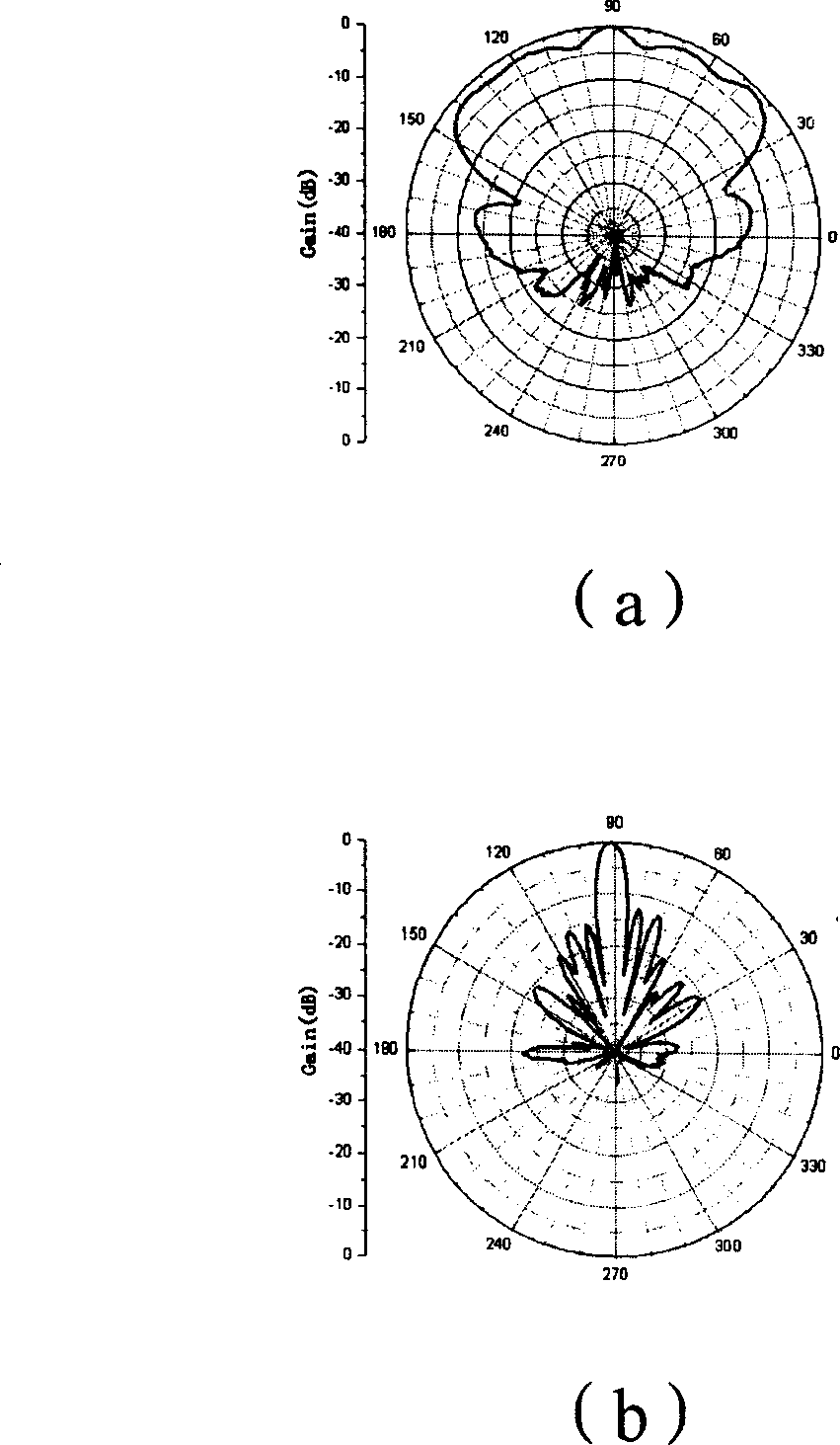
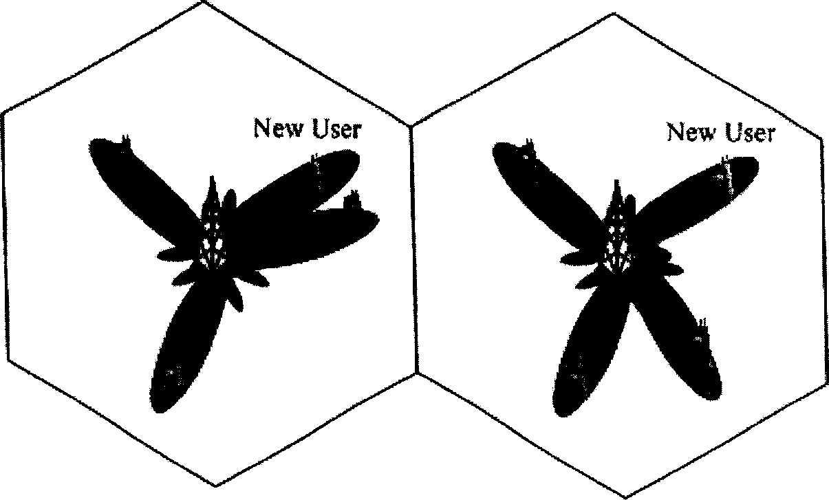
Technical field [0001] The invention relates to a smart antenna technology of a time division duplex-synchronous code division multiple access (TD-SCDMA) mobile communication system, and particularly relates to a method for adaptively adjusting the beam width of the smart antenna. Background technique [0002] At present, the smart antenna used in the base station of the TD-SCDMA system can generate two beams. One is an omnidirectional beam, which is mainly used for downlink pilot or broadcast channels. This kind of beam does not need to generate a directional beam according to the current location of the user. ,Such as figure 1 As shown in a; the other is a directional service beam, which is mainly used for normal service communication with user equipment (UE), such as figure 1 Shown in b. [0003] When the base station uses the above-mentioned smart antennas to communicate with different UEs for normal services, the base station will generate different service beams for each ...

Claims


Application Information

Patent Timeline
Patent Type & Authority Applications(China)
IPC IPC(8): H01Q3/00H04B7/02
Inventor 王斌
Owner POTEVIO INFORMATION TECH
Why Eureka
Try Eureka