Optical receiving system of doppler wind lidar

A Doppler wind measurement and lidar technology, which is applied in the field of Doppler wind measurement and lidar optical receiving systems, can solve the problems of decreased receiving efficiency of an optical path receiving device, loss of backscattered light signals, unfavorable FP etalon processing, etc. , to achieve the effect of being beneficial to the adjustment of the optical path, reducing the loss of the optical signal, and improving the frequency locking efficiency

Inactive Publication Date: 2011-10-26
UNIV OF SCI & TECH OF CHINA
View PDF1 Cites 26 Cited by
  • Summary
  • Abstract
  • Description
  • Claims
  • Application Information

AI Technical Summary

Problems solved by technology

[0004] At present, the double-edge technology of FP etalon adopted internationally, the signal received by the telescope 1 is sent to the three channels of the edge etalon respectively through the optical beam splitter, and the three channels include: two signal channels and one locking channel , due to the optical signal in the locked channel, the light from the backscattered light reflected back near the telescope, that is, part of the backscattered light signal is distributed to the locked channel, which leads to the loss of the backscattered light signal, which in turn leads to the loss of the optical path receiving device The receiving efficiency is reduced; since the three channels in the FP etalon have the same caliber and are distributed on one substrate of the etalon, the size of the FP etalon is larger, which is not conducive to the processing of the FP etalon, and increases the processing cost; moreover, The three channels in the FP etalon have the same caliber and are distributed on one FP etalon substrate. The optical path crosses a lot in space, which makes the optical path system more complicated and is not conducive to the adjustment of the optical path.

Method used


Image

  • Optical receiving system of doppler wind lidar
  • Optical receiving system of doppler wind lidar
  • Optical receiving system of doppler wind lidar

Examples


Embodiment Construction

[0044] In order to make the above objects, features and advantages of the present application more obvious and comprehensible, the present application will be further described in detail below in conjunction with the accompanying drawings and specific implementation methods.

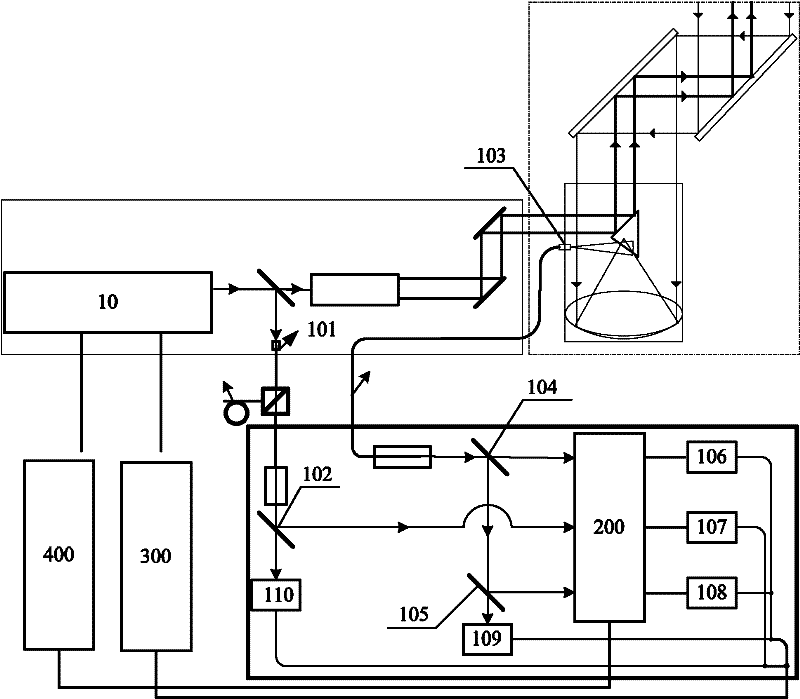
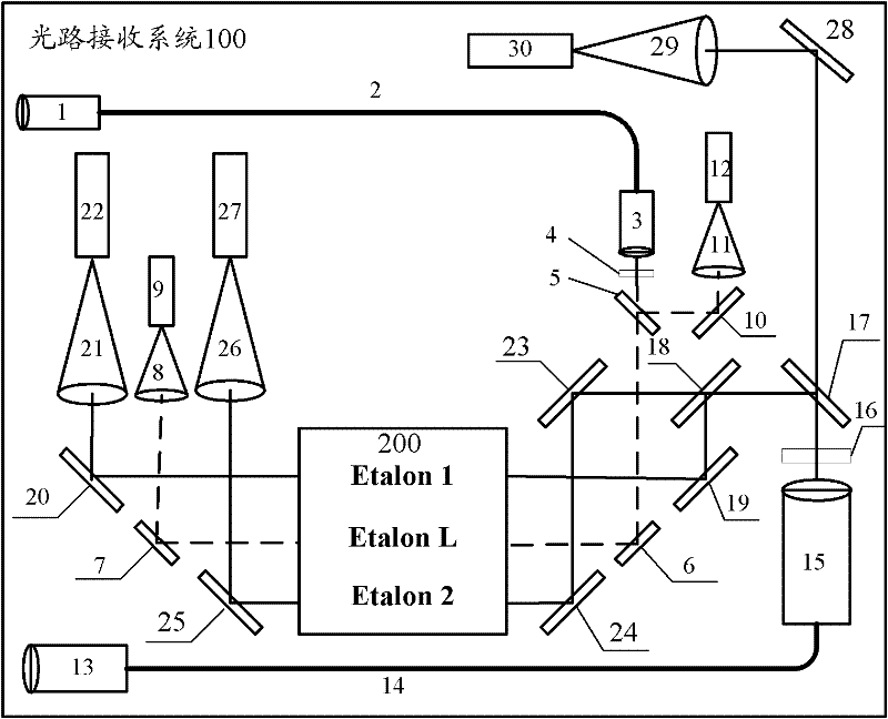
[0045] See figure 1 , figure 1 It is a schematic structural diagram of a Doppler wind lidar optical receiving system according to an embodiment of the present application. The system includes:

[0046] Receiving optical path system 100, FP etalon 200, detection acquisition system 300, and control system 400, wherein:

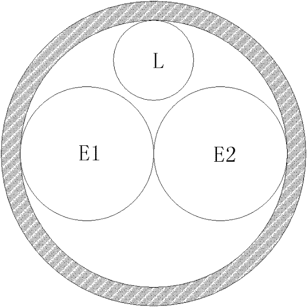
[0047] The FP etalon 200 includes three channels, namely the first signal channel E1, the second signal channel E2 and the locking channel L, wherein: the first signal channel E1 and the second signal channel E2 are located side by side on the center line of the FP etalon aperture, The locking channel L is located above the first signal channel E1 and the second signal channel E2, so tha...


PUM


Abstract

The application discloses an optical receiving system of doppler wind lidar (DWL). According to the invention, two independent optical paths are employed; a fraction of lights, which are ejected by a laser, are collected by a first coupler; and the collected lights pass optical elements including a spectroscope and a reflective mirror and the like and then penetrate into a locking channel of a Fabry-Perot (FP) etalon; atmosphere backward dispersion lights are collected by a second coupler; the collected atmosphere backward dispersion lights pass the optical elements including the spectroscope and the reflective mirror and the like and then penetrate into two signal channels of the FP etalon. Because the optical signals of the locked channel is dispersion lights from a light-emitting window of the laser, so that optical light loss of signal channels is reduced. Moreover, the intensity of the portion of the dispersion lights is larger than the intensity of the atmosphere backward dispersion lights, so that a frequency locking efficiency is improved and a measurement precision of an atmospheric wind field can also be enhanced. Meanwhile, a caliber of the locking channel of the FP etalon can be reduced, so that processing cost of the FP etalon is substantially reduced; besides, the optical path system is simple, which is favor of adjustment of the optical path.

Description

technical field [0001] The present application relates to the technical field of laser radar, in particular to an optical receiving system of Doppler wind measuring laser radar. Background technique [0002] Rayleigh scattering refers to elastic light scattering where the wavelength of the scattered light is equal to the wavelength of the incident light, and the scattering particles are much smaller than the wavelength of the incident light, and there is no frequency shift. Rayleigh scattering wind lidar is a detection method of atmospheric wind field, which is realized by direct measurement. Its principle is: to reflect the atmospheric wind speed through the group velocity of atmospheric molecules. The transmitter emits laser light into the atmosphere, and the laser light encounters atmospheric molecules to produce backscattering, and the backscattered laser signal is received by the receiver. If the atmospheric molecules move due to wind, the Rayleigh scattering signal rec...

Claims


Application Information

Patent Timeline
Patent Type & Authority Applications(China)
IPC IPC(8): G01S7/48G01S7/481G01S17/95
CPCY02A90/10
Inventor 窦贤康孙东松舒志峰薛向辉夏海云陈廷娣
Owner UNIV OF SCI & TECH OF CHINA
Why Eureka
Try Eureka