Device and method for detecting a dripper

Active Publication Date: 2016-09-01
MAILLEFER SA MAILLEFER SA
View PDF2 Cites 1 Cited by
  • Summary
  • Abstract
  • Description
  • Claims
  • Application Information

AI Technical Summary

Benefits of technology

The patent text describes a laser-based dripper detection device and a rotary based pipe drilling device. The laser detection device can quickly and accurately detect small changes in the pipe profile caused by a dripper, without interfering with the pipe's high-speed operation. The rotary drilling device is also efficient and precise, with no need for back-and-forth motion that causes vibrations. The device uses an alternating rotary motion that allows for a shorter time between drilling tool movements, reducing the risk of damage to the dripper. A stabilizing unit ensures a constant orientation and distance of the pipe section facing the laser detection unit, minimizing the risk of drilling out of the collecting chamber of the dripper or damaging the pipe without a dripper. Overall, these technical effects improve the accuracy and efficiency of the drilling process.

Problems solved by technology

Also a laser based dripper detection device is an optical detection means which does not vibrate whereas a lot of known dripper detection devices are mechanically working and are inherently subject to vibrations when working at high speed.

Method used


Image

  • Device and method for detecting a dripper
  • Device and method for detecting a dripper
  • Device and method for detecting a dripper

Examples


Embodiment Construction

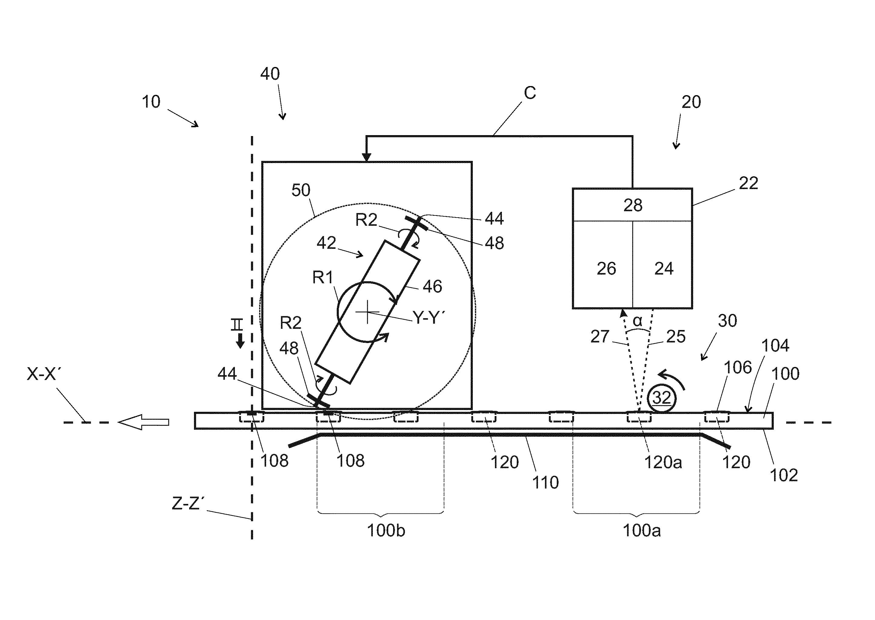
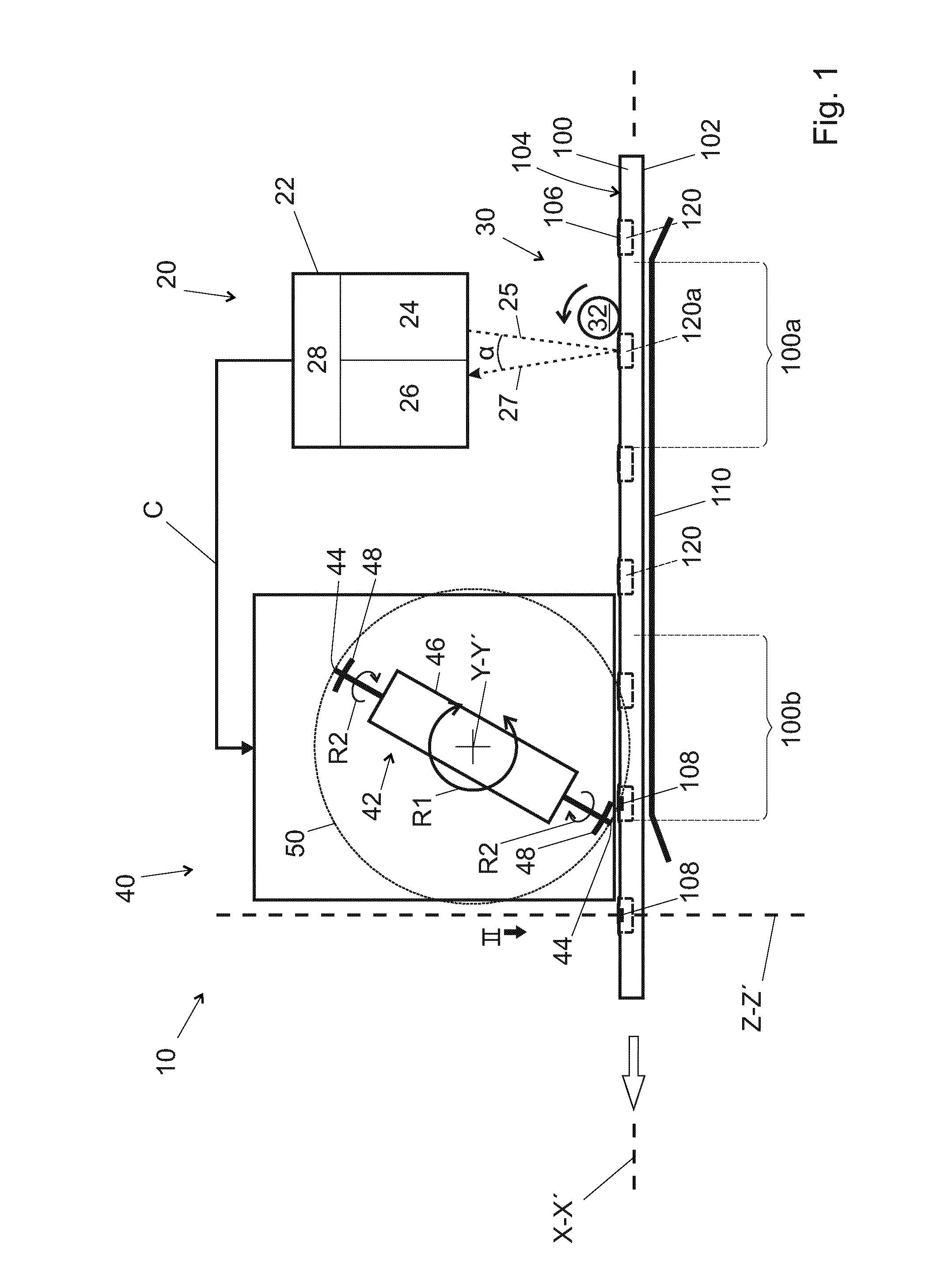
[0051]The irrigation pipe drilling system 10 schematically shown in FIG. 1 comprises a dripper detection device 20 (on the right) and a pipe drilling device 40 (on the left). This irrigation pipe drilling system 10 is placed facing an irrigation pipe 100 running along a path whose portion facing irrigation pipe drilling system 10 is represented in a non-limitative way as being horizontal and linear, parallel to a circulation direction shown here identical to an axis X-X′. This irrigation pipe 100 is supported by a support element 110.

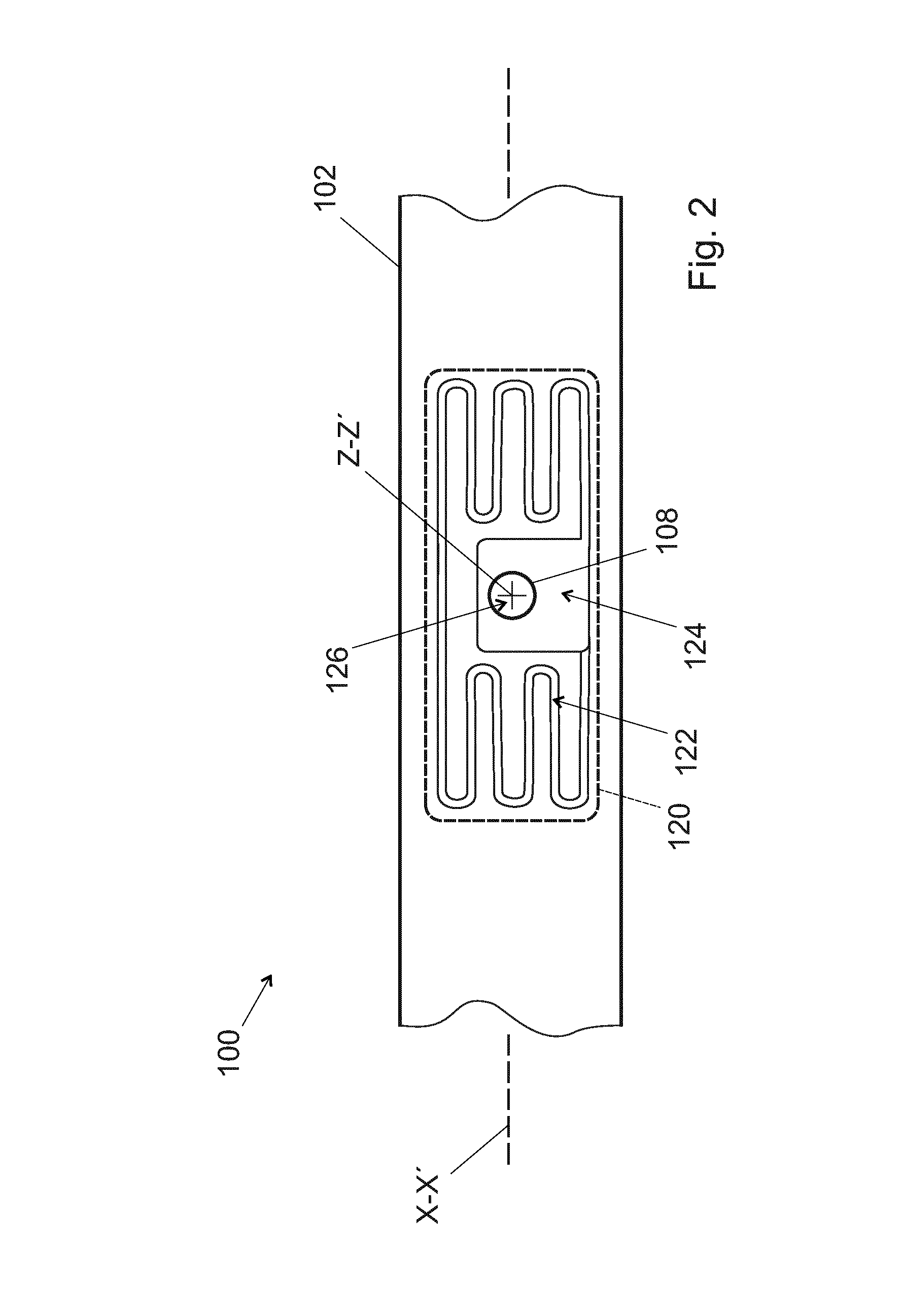
[0052]The irrigation pipe 100 contains drippers 120 placed inside said irrigation pipe 100 while being fixed to the inner face of the pipe wall 102. As shown in FIG. 1, preferably, drippers 120 are placed inside said irrigation pipe 100 at regular and constant intervals in the running portion of the pipe. In some cases, the drippers 120 are placed inside said irrigation pipe 100 at regular but not constant intervals in the running portion of the pipe: f...


PUM


Abstract

A dripper detection device for an irrigation pipe manufacturing system includes a continuous pipe feeder capable of making a pipe equipped with drippers, each dripper having a water outlet. The pipe circulates along a predetermined circulation direction (X-X′) while keeping the drippers' water outlets in a predetermined orientation. The dripper detection device includes a laser detection unit with a laser source emitting a laser beam directed to the pipe outer face location where drippers are present at regular intervals, and a laser signal receiver which receives and analyses the laser beam reflected on the pipe outer face to provide a transformed reflected signal which contains information about the passage of each dripper facing said laser detection unit.

Description

FIELD OF THE INVENTION[0001]The present invention concerns a method for manufacturing an irrigation pipe, in particular a drip irrigation pipe, and a system for manufacturing this irrigation pipe. More precisely, the present invention concerns also a dripper detection method and a device for detecting a dripper, as well as a pipe drilling method and a device for drilling a pipe at a dripper location.DESCRIPTION OF RELATED ART[0002]Some irrigation techniques use so-called “drip” irrigation pipes or hoses. The expression “drip irrigation pipe” indicates in this context an irrigation pipe, e.g. made of polymeric material, pierced at pre-determined intervals by holes of small diameter, through which water can flow towards the ground. A dripper or drip element, which is a flow limiter, can be provided at each hole for precisely controlling the flow from the holes. It is generally made of plastic material and it is attached to the inner wall of the irrigation pipe during its manufacturing...

Claims


Application Information

Patent Timeline
IPC IPC(8): A01G25/02G01B11/30G01B11/14
CPCA01G25/026G01B11/303G01B11/14
Inventor KURTH, FLORIANDONZE, AXEL
Owner MAILLEFER SA MAILLEFER SA
Why Eureka
Try Eureka