Radial telescope bushing for steering column

a technology for radial telescopes and steering columns, applied in the direction of mechanical equipment, rigid support of bearing units, transportation and packaging, etc., can solve the problems of poor wear characteristics

Active Publication Date: 2016-09-01
STEERING SOLUTIONS IP HLDG
View PDF2 Cites 29 Cited by
  • Summary
  • Abstract
  • Description
  • Claims
  • Application Information

AI Technical Summary

Problems solved by technology

However, the injection process and resulting telescope bushing may be greatly influenced by environmental variables, which may result in poor wear characteristics.

Method used


Image

  • Radial telescope bushing for steering column
  • Radial telescope bushing for steering column
  • Radial telescope bushing for steering column

Examples


Embodiment Construction

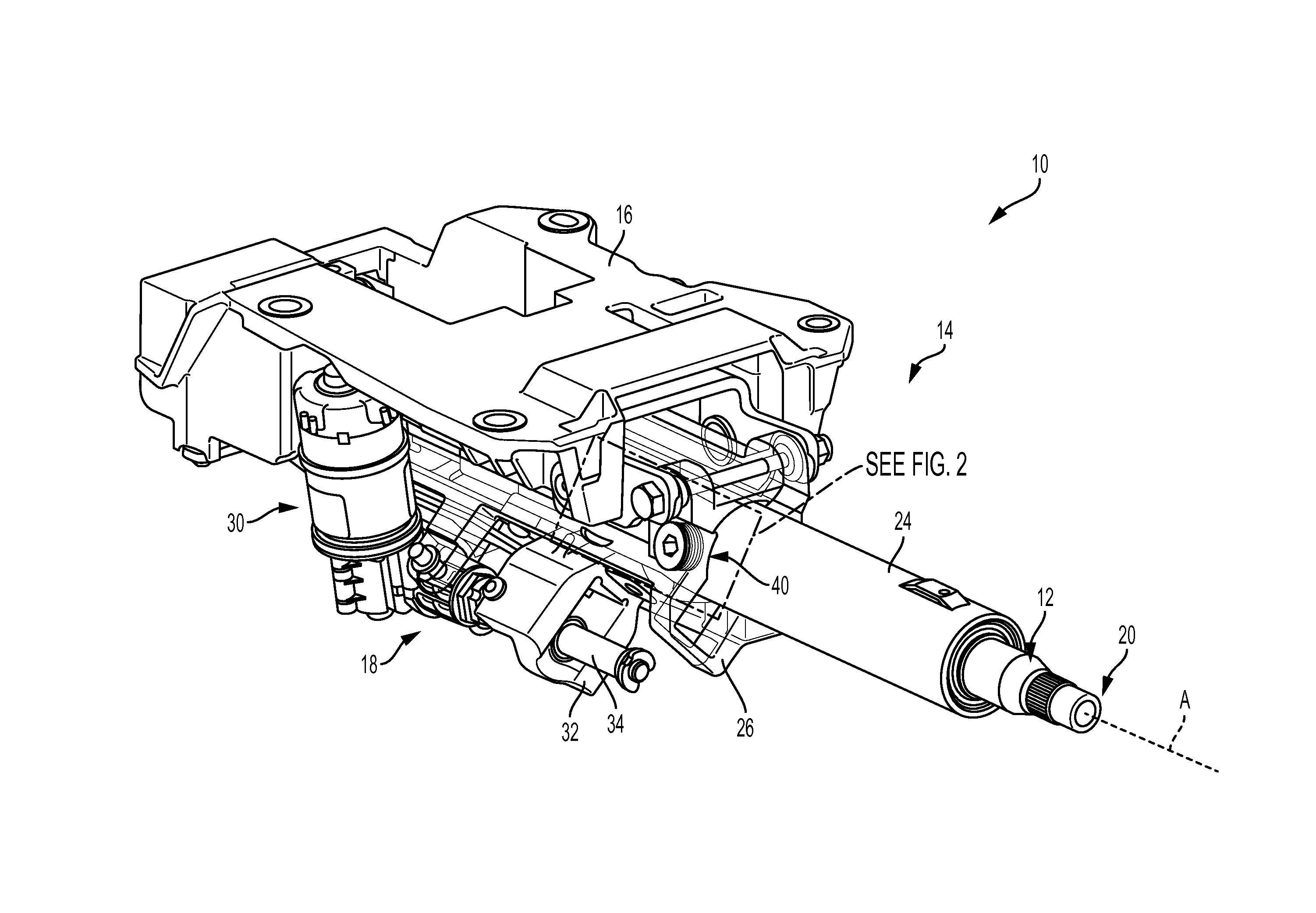
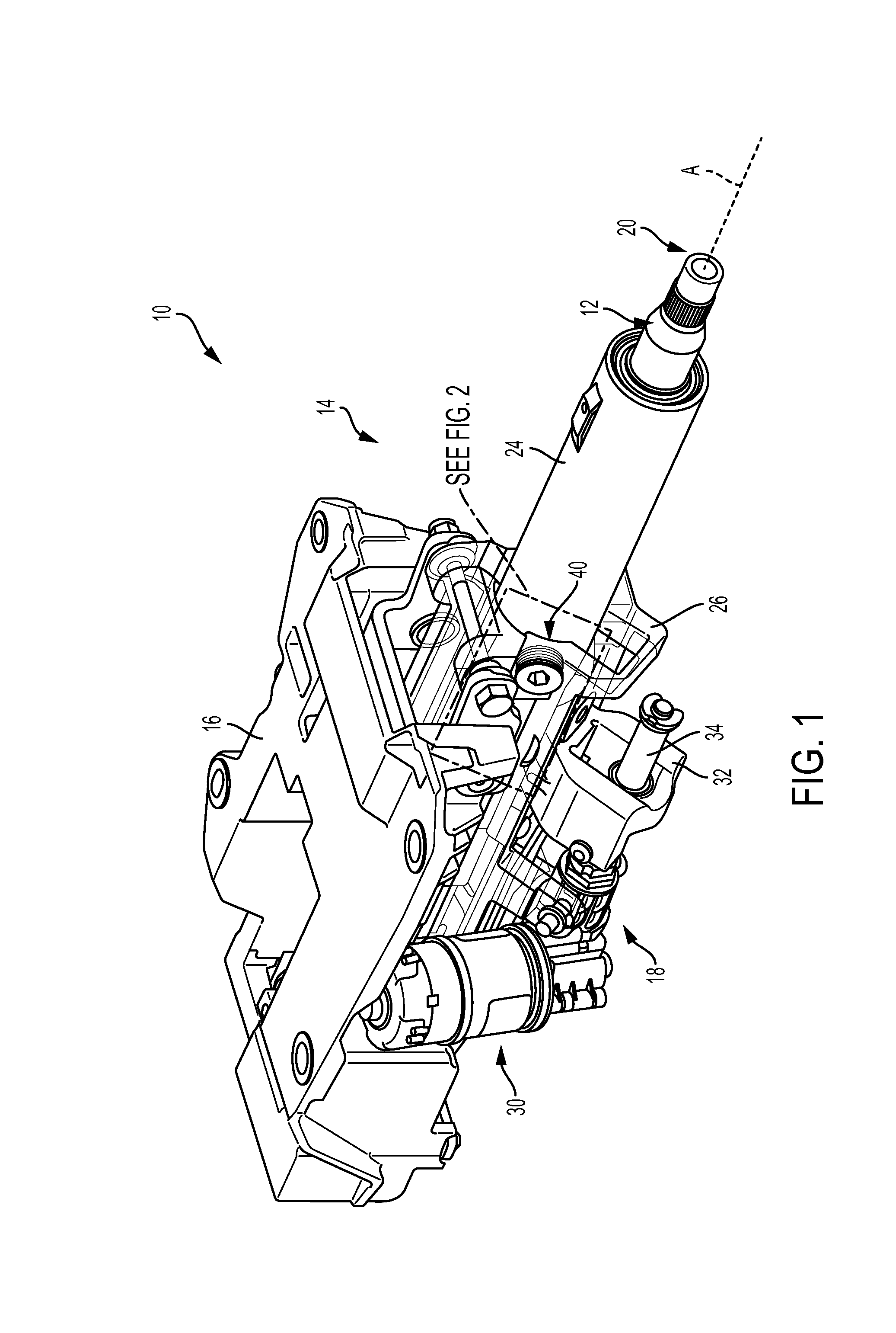
[0015]Referring now to the Figures, where the invention will be described with reference to specific embodiments, without limiting same, FIG. 1 illustrates an exemplary steering column assembly 10 for a vehicle (not shown). As shown in FIG. 1, steering column assembly 10 generally includes a steering column shaft 12, a jacket assembly 14 positioned about shaft 12, a mounting bracket 16, and a telescope actuator assembly 18.

[0016]Steering shaft 12 extends along an axis ‘A’, and a steering wheel (not shown) is attached to a first end 20 of shaft 12 while an opposite second end (not shown) of shaft 12 is coupled to a steering gear (not shown). Jacket assembly 14 surrounds and supports shaft 12 and includes an upper jacket 24 and a lower jacket 26. Mounting bracket 16 supports jacket assembly 14 and mounts assembly 14 to the vehicle.

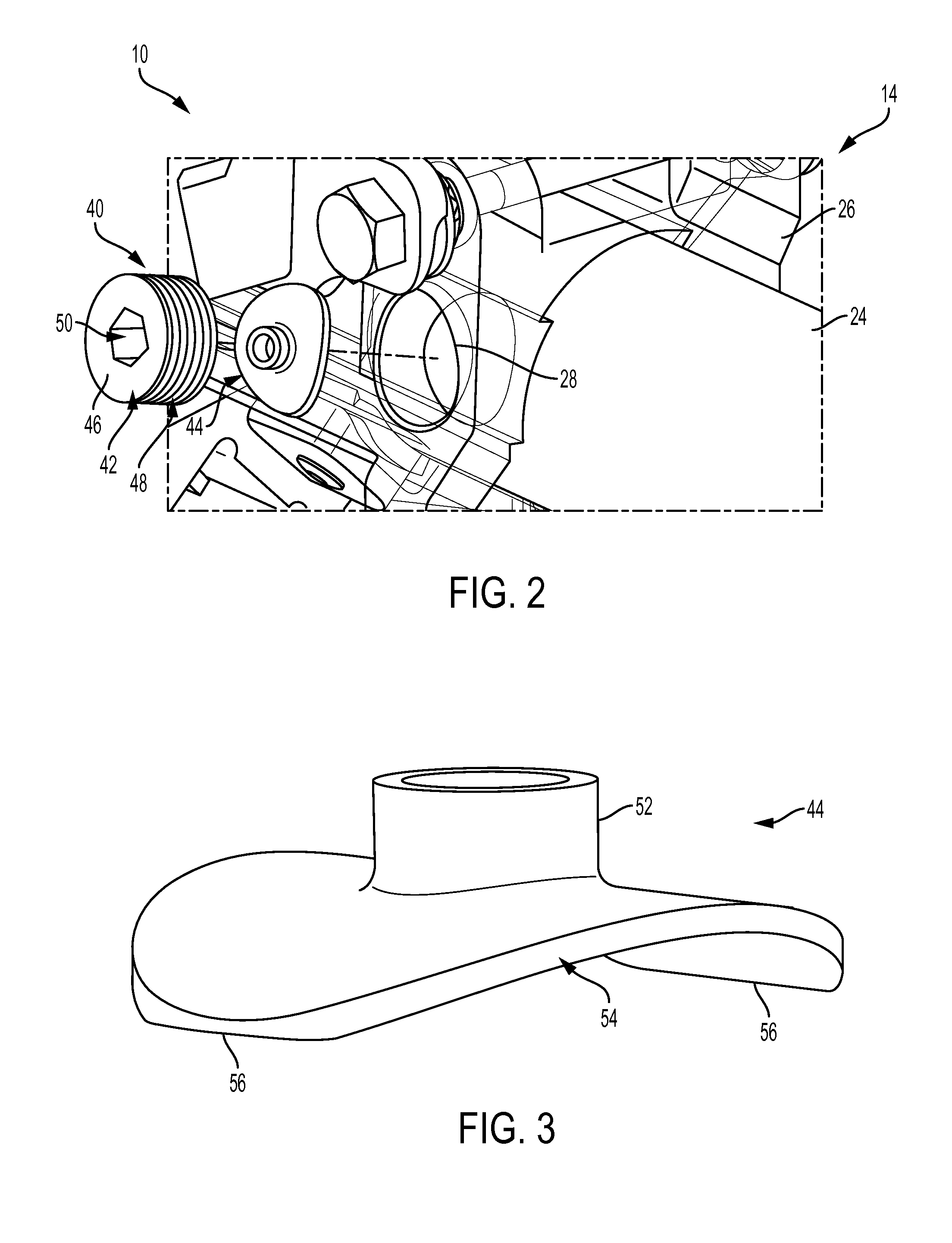
[0017]In the embodiment shown, telescope actuator assembly 18 includes an electric motor 30 and gearing (not shown) for transferring rotatory motion of elec...


PUM


Abstract

A bushing assembly for a steering column having a fixed jacket and a telescope jacket is provided having a set screw configured for insertion into the fixed jacket, and a radial telescope bushing co-acting with the set screw and having a post and a curved bushing portion configured to pre-load the radial telescope bushing against the telescope jacket to provide a lash-free interface between the fixed jacket and the telescope jacket.

Description

FIELD OF THE INVENTION[0001]The following description relates to steering columns for motor vehicles and, more specifically, to a telescope bushing assembly for a steering column.BACKGROUND[0002]Some known steering columns for motor vehicles are provided with mechanisms for adjusting the steering column position by an operator of the motor vehicle. Available adjustments typically include a telescoping adjustment in which the steering column is extended toward the operator or retracted away from the operator, and a tilt or rake adjustment in which an angular position of the steering column is changed relative to the operator.[0003]In some known systems, a telescope bushing is used to provide a compliant bushing material to facilitate telescope action. In order to provide for a lash-free telescope joint, the telescope bushing is constricted around a telescoping member by way of injected material and pressurized into a cavity between the telescope bushing and a fixed jacket component. ...

Claims


Application Information

Patent Timeline
Patent Type & Authority Applications(United States)
IPC IPC(8): F16C29/02B62D1/185F16C43/02F16C29/00
CPCF16C29/02F16C43/02B62D1/185F16C29/001B62D1/181F16C29/123F16C35/02F16C2326/24
Inventor CAVERLY, JACOB A.
Owner STEERING SOLUTIONS IP HLDG
Why Eureka
Try Eureka