Tensioning rail with bayonet catch

a technology of a bayonet and a sleeve, which is applied in the direction of belts/chains/gearrings, mechanical devices, belts/chains/gears, etc., can solve the problems of reducing the service life of the housing, so as to achieve reliable operation

Inactive Publication Date: 2016-09-01
IWIS MOTORSYSTEME GMBH & CO KG
View PDF7 Cites 10 Cited by
  • Summary
  • Abstract
  • Description
  • Claims
  • Application Information

AI Technical Summary

Benefits of technology

[0004]Hence, it is the object of the present invention to realize a tensioning rail uni...

Problems solved by technology

The tensioning rail is pivoted together with the fork head and the outer surface of the fork head enters into contact with a suitably adapted housing contour such that it is no longer possible to release the tensioning rail at the operating position.
The amount of ...

Method used


Image

  • Tensioning rail with bayonet catch
  • Tensioning rail with bayonet catch
  • Tensioning rail with bayonet catch

Examples


Embodiment Construction

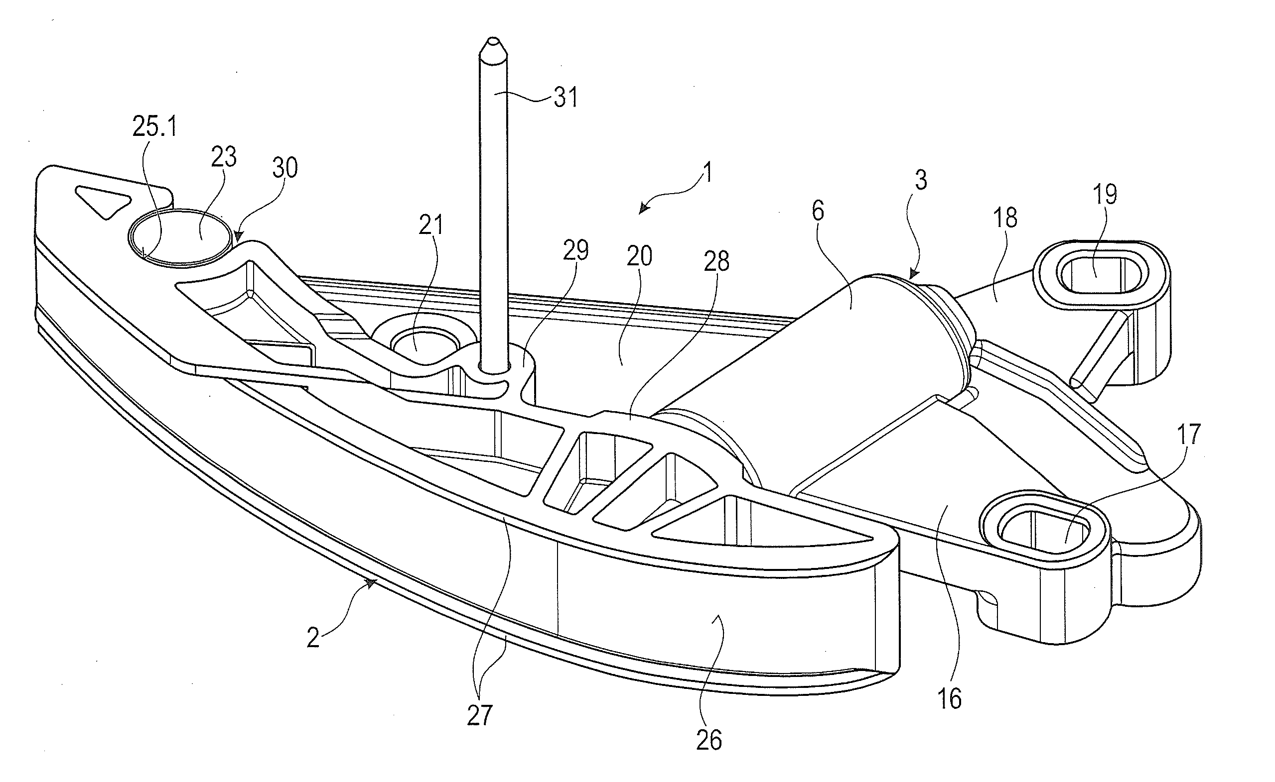
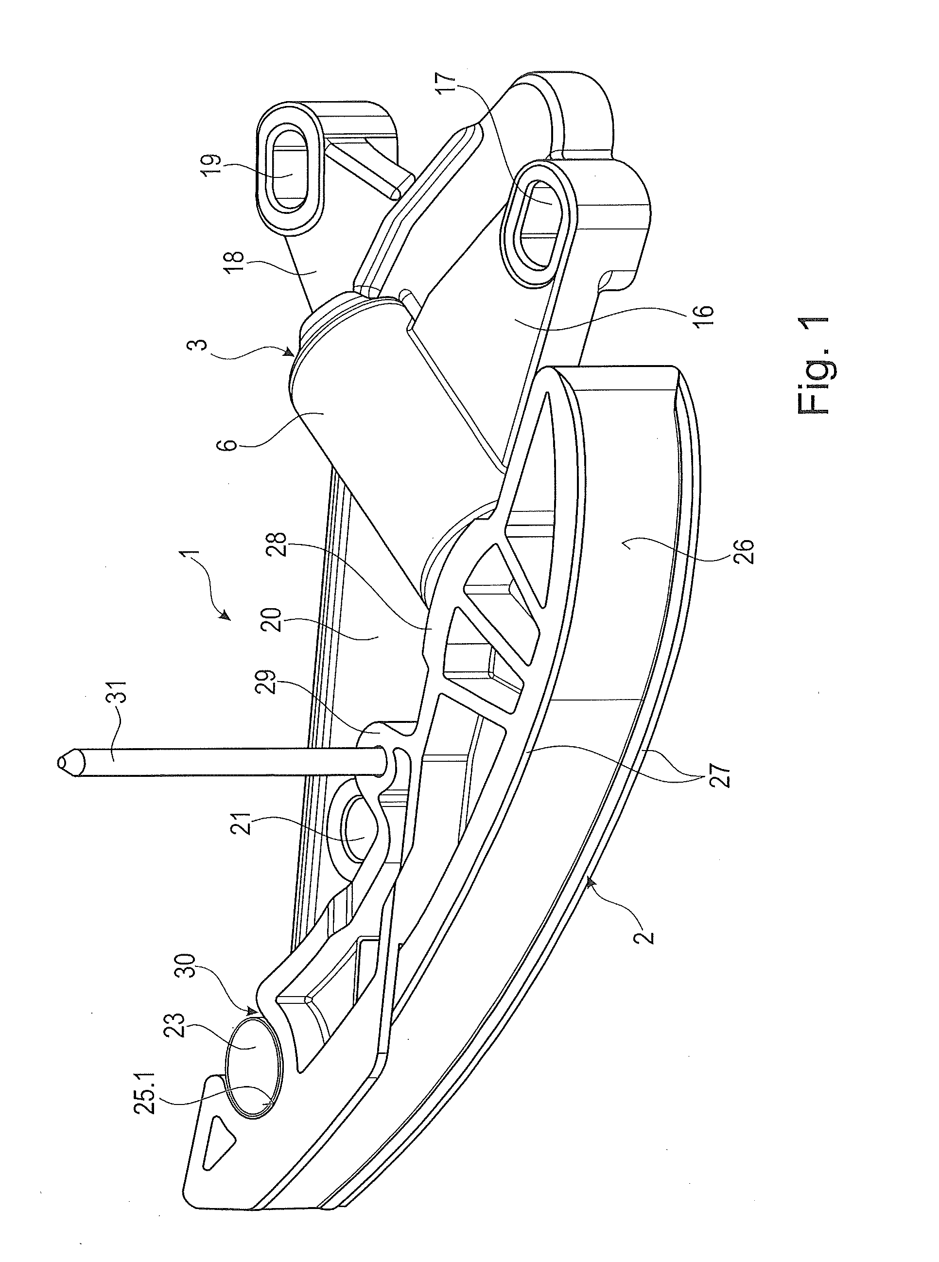
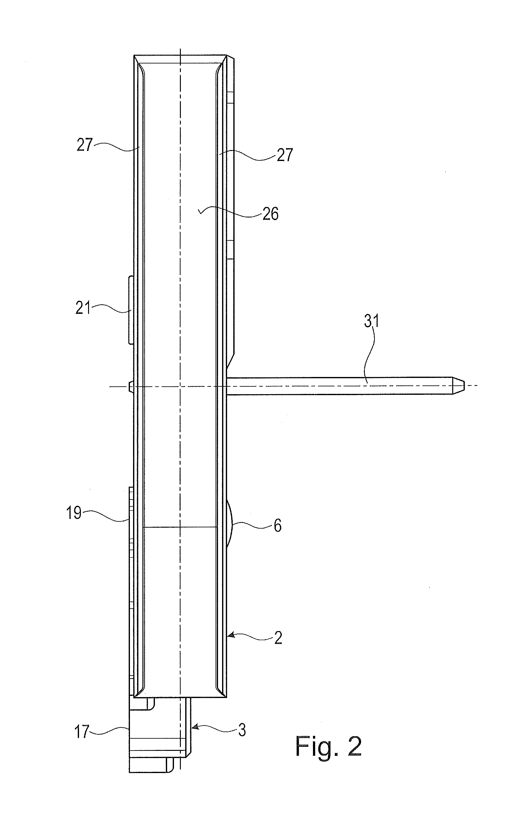
[0027]The tensioning rail unit 1 shown in FIGS. 1 to 5 is used in a chain drive of an internal combustion engine (not shown). One possibility of use is e.g. the oil pump drive. The tensioning rail unit 1 comprises a pivotably arranged tensioning rail 2 and a tensioner 3 coupled thereto. The tensioning rail 2 consists of plastic material and is produced by means of injection molding. The tensioner 3 comprises a housing 4 produced by means of a metal die casting process and a tensioning piston 5 displaceably guided in said housing 4 (cf. FIG. 4). To this end, the housing 4 comprises a cylindrical housing section 6 provided with a piston bore 7 in which the tensioning piston 5 is guided. The tensioning piston 5 is configured as a hollow piston and comprises in the interior thereof a compression spring 8 resting on the bottom of the piston bore 7, a vent valve disk 9 and a vent valve body 10 preloaded by means of a valve spring 11. The valve spring 11 is guided in a bore, which, in turn...


PUM


Abstract

A tensioning rail unit for an endless drive, comprises a tensioning rail arranged for pivoting about a pivotable arrangement and a tensioner acting on the tensioning rail and including a housing and a tensioning piston guided in the housing, wherein the housing has an arm having attached thereto a first element of the pivotable arrangement, the tensioning rail has attached thereto a second element of the pivotable arrangement, and the first and second elements are adapted to be mounted at a mounting position by means of a plug-in movement and to be transferred to a locked operating position by means of a subsequent pivoting movement. The first or the second element is configured as an accommodation pocket open in the direction of the pivot axis, the accommodation pocket being provided with a pocket opening having a lateral opening which is open over an angular range of less than 180°, and the respective other element is configured as a pivot pin held by a fastening section dimensioned at the mounting position, that can be attached in the direction of the pivot axis due to the lateral opening of the accommodation pocket and engages then, by the subsequent pivoting movement, a locking slot intersecting the pocket opening, the locking slot being formed in the accommodation pocket.

Description

CROSS-REFERENCE TO RELATED APPLICATION[0001]This application claims priority to foreign German patent application No. 102015002567.8, filed on Feb. 27, 2015, the disclosure of which is incorporated by reference in its entirety.FIELD OF THE INVENTION[0002]The present invention relates to a tensioning rail unit for an endless drive, comprising a tensioning rail arranged for pivoting about a pivotable arrangement and a tensioner acting on the tensioning rail and including a housing and a tensioning piston guided in said housing, wherein the housing has an arm having attached thereto a first element of the pivotable arrangement, the tensioning rail has attached thereto a second element of the pivotable arrangement, and the first and second elements are adapted to be mounted at a mounting position by means of a plug-in movement and to be transferred to a locked operating position by means of a subsequent pivoting movement.BACKGROUND[0003]Such tensioning rail units are used especially for...

Claims


Application Information

Patent Timeline
IPC IPC(8): F16H7/08
CPCF16H7/08F16H2007/0893F16H2007/0872F16H7/18F16H2007/0842F16H2007/185F16H2007/0814F16H2007/0817
Inventor GUYOT, YANNICKVON VOPELIUS-FELDT, PHILLIPP
Owner IWIS MOTORSYSTEME GMBH & CO KG
Why Eureka
Try Eureka