Compound bow

a bow and compound technology, applied in bows/crossbows, white arms/cold weapons, weapons, etc., can solve the problems of insufficient strength of bows and drop of arrow accuracy, and achieve the effect of minimizing twisting of bows, inherent strength of bows, and enhancing accuracy of arrows

Inactive Publication Date: 2016-09-01
WIN & WIN
View PDF3 Cites 0 Cited by
  • Summary
  • Abstract
  • Description
  • Claims
  • Application Information

AI Technical Summary

Benefits of technology

[0009]To solve the above conventional problems or defects, it is an object of the present invention to provide a compound bow to minimize twisting of the bow, to exhibit inherent strength of the bow, and to improve accuracy of an arrow.
[0010]To accomplish the above and other objects of the present invention, according to an aspect of the present invention, there is provided a compound bow comprising: a bow main body including a handle at a central portion of which a grip portion is formed and a pair of limbs that are respectively coupled to both ends of the handle; upper and lower pulley assemblies each including a pulley that is rotatably coupled to a rotating shaft formed on the rear end of each limb, and a cam that is coupled to the pulley and is rotated with the pulley; a bowstring whose either end is wound on and coupled to the pulley of each of the upper and lower pulley assemblies; and first and second cam cables that are wound around the cam of each of the upper and lower pulley assemblies as the bowstring is pulled, in which one end of each of the first and second cam cables is coupled to one of the upper and lower pulley assemblies, and the other end thereof is coupled to the other of the upper and lower pulley assemblies or the rotating shaft of the other of the upper and lower pulley assemblies, wherein the respective cams are provided on one side and the other side of the pulley around the pulley in the lower pulley assembly, the first cam cable comprises: a central cable; an upper cable that is connected to the upper side of the central cable; and a lower cable that is connected to the lower side of the central cable, the upper cable comprises: a one-side cable portion and the other-side cable portion that are positioned on both sides of the pulley of the upper pulley assembly, in which either end of the upper cable is coupled to the rotating shaft to which the upper pulley assembly is coupled at either side of the pulley of the upper pulley assembly, the lower cable comprises: a one-side cable portion and the other-side cable portion that are positioned on both sides of the pulley of the lower pulley assembly, in which either end of the lower cable is coupled to a fixing projection that is formed at either side of the pulley of the lower pulley assembly, and the one-side cable portion and the other-side cable portion of the lower cable are supported by a spacing member so as to maintain a constant interval, to thus make the one-side cable portion and the other-side cable portion of the lower cable wound on the respective cams formed at both sides of the pulley of the lower pulley assembly, while maintaining the one-side cable portion and the other-side cable portion of the lower cable to have the constant interval by the spacing member, as the bowstring is pulled, to thereby minimize twisting of the bow limbs and improve accuracy of an arrow.
[0018]Preferably but not necessarily, the respective cams of each of the pulley assemblies comprise: a cam cable support portion supporting the cam cable; a cam module that is movably coupled in an arc trajectory on the pulley to which the cams are coupled; and a fixing unit that fixes the cam module at a desired position on the pulley in order to adjust a pulling length of a let-off state, in which the cam cable is supported on the cam cable support portion and then is wound on the outer circumferential surface of the cam module, when the bowstring is pulled, the second cam cable is coupled to the fixing projection that is formed in the cam module and moves along as the cam module moves, is wound on a cam cable winding portion that is penetrated by the rotating shaft via a compensation projection, and then extends toward the other side pulley assembly, and a front portion of the cam module is in contact with the second cam cable and thus the second cam cable is bent when the cam module is moved in which one end of the second cam cable is coupled to the fixing projection of the cam module in order to adjust the draw length of the let-off state, to thus release the second cam cable from the cam cable winding portion via the compensating projection from the fixing projection to which the second cam cable is coupled, to thereby maintain constant tension of the cam cable and keep the power of the bow.
[0022]According to another aspect of the present invention, there is also provided a compound bow comprising: a bow main body including a handle at a central portion of which a grip portion is formed and a pair of limbs that are respectively coupled to both ends of the handle; upper and lower pulley assemblies each including a pulley that is rotatably coupled to a rotating shaft formed on the rear end of each limb, and a cam that is coupled to the pulley and is rotated with the pulley; a bowstring whose either end is wound on and coupled to the pulley of each of the upper and lower pulley assemblies; and first and second cam cables that are wound around the cam of each of the upper and lower pulley assemblies as the bowstring is pulled, in which one end of each of the first and second cam cables is coupled to one of the upper and lower pulley assemblies, and the other end thereof is coupled to the other of the upper and lower pulley assemblies or the rotating shaft of the other of the upper and lower pulley assemblies, wherein the respective cams are provided on one side and the other side of each of the pulleys around the respective pulleys in the upper and lower pulley assemblies, each of the first and second cam cables comprises: a first cable that is coupled with one pulley assembly; and a second cable that is connected to the first cable and coupled with the other pulley assembly, the first cable comprises: a one-side cable portion and the other-side cable portion that are positioned on both sides of the pulley, in which either end of the first cable is coupled to a fixing projection that is formed at either side of the pulley of the pulley assembly to which the first cable is coupled, and the one-side cable portion and the other-side cable portion of the first cable are supported by a spacing member so as to maintain a constant interval, to thus make the one-side cable portion and the other-side cable portion of the first cable wound on the respective cams formed at both sides of the pulley of the pulley assembly to which the first cable is coupled, while maintaining the one-side cable portion and the other-side cable portion of the first cable to have the constant interval by the spacing member, as the bowstring is pulled, to thereby minimize twisting of the bow limbs and improve accuracy of an arrow.
[0024]Preferably but not necessarily, the respective cams of each of the pulley assemblies comprise: a cam cable support portion supporting the cam cable; a cam module that is movably coupled in an arc trajectory on the pulley to which the cams are coupled; and a fixing unit that fixes the cam module at a desired position on the pulley in order to adjust a draw length of a let-off state, in which the cam cable is supported on the cam cable support portion and then is wound on the outer circumferential surface of the cam module, when the bowstring is pulled, the second cable is coupled to the fixing projection that is formed in the cam module and moves along as the cam module moves, is wound on a cam cable winding portion that is formed around the rotating shaft via a compensation projection, and then extends toward the other side pulley assembly, and a front portion of the cam module is in contact with the second cable and thus the second cable is bent when the cam module is moved in which one end of the second cable is coupled to the fixing projection of the cam module in order to adjust the draw length of the let-off state, to thus release the second cable from the cam cable winding portion via the compensating projection from the fixing projection to which the second cable is coupled, to thereby maintain constant tension of the cam cable and keep the power of the bow.
[0025]As described above, the present invention provides a compound bow capable of minimizing twisting of the bow when used, exhibiting an inherent strength of the bow and simultaneously enhancing accuracy of an arrow with an improved synchronizing.

Problems solved by technology

As a result, the inherent strength of the bow is not exhibited and the accuracy of the arrows is also dropped.

Method used


Image

  • Compound bow
  • Compound bow
  • Compound bow

Examples


first embodiment

[0040]Hereinbelow, a compound bow according to the present invention will be described in more detail with reference to the accompanying drawings.

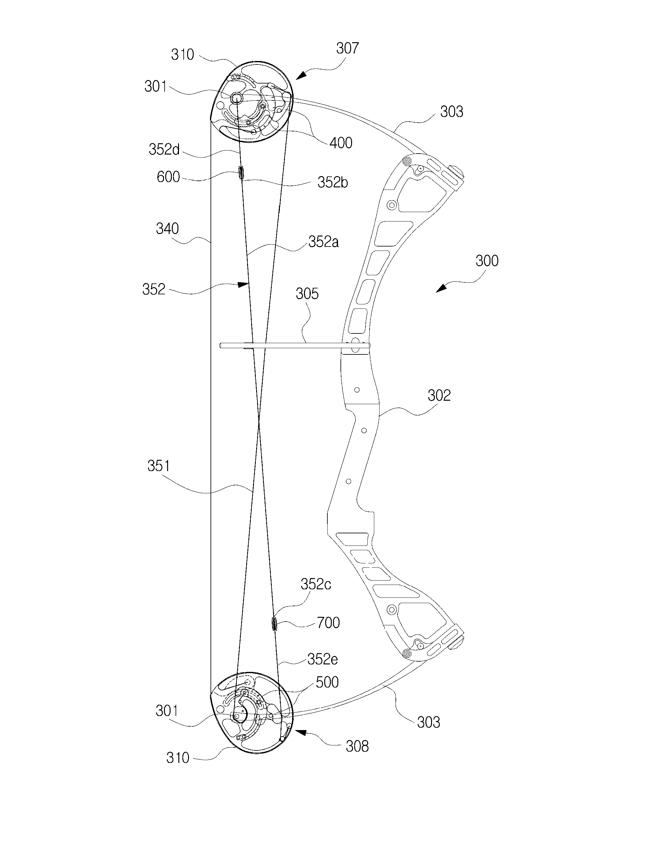
[0041]Referring to FIGS. 4 to 12, a compound bow according to a first embodiment of the present invention comprises: a bow main body 300 including a pair of limbs 303 that are respectively coupled to both ends of a handle 302; upper and lower pulley assemblies 307 and 308 that are respectively coupled to the rear end of each limb 303; a bowstring 340; first and second cam cables 352 and 351 that are wound around a cam 400, 500 of each of the upper and lower pulley assemblies 307 and 308 as the bowstring 340 is pulled.

[0042]As shown, the compound bow according to the present invention will be described below in more detail. First, the bow main body 300 includes a handle 302 at a central portion of which a grip portion is formed so as to be gripped by a user, and a pair of limbs 303 that are respectively coupled to both ends of the handle 30...

second embodiment

[0077]In addition, when the first and second cam cables 353 and 354 in the second embodiment will be described, as shown in FIG. 13, the first cam cable 353 includes a first cable 353b, and a second cable 353a that is connected to the first cable 353b by a spacing member (a ring 700 in some embodiments of this invention), and the second cam cable 354 includes a first cable 354b, and a second cable 354a that is connected to the first cable 354b by a spacing member (a ring 700 in some embodiments of this invention). The first and second cam cables 353 and 354 have a vertically symmetric image.

[0078]Therefore, the first cam cable 353 will be described as an example. The second cable 353a in the first cam cable 353 is extended to the upper pulley assembly 308 and is wound around the cam cable winding portion 320 through which the rotating shaft 301 is penetrated in the upper pulley 310, and then the upper end of the second cable 353a is fixed to the fixing projection 530 formed in the u...


PUM


Abstract

Provided is a compound bow including: first and second cam cables between upper and lower pulley assemblies, wherein the lower cable of the first cam cable comprises: a one-side cable portion and the other-side cable portion on both sides of the pulley, in which either end of the lower cable is coupled to a fixing projection formed at either side of the pulley, and the one-side cable portion and the other-side cable portion of the lower cable are supported by a spacing member so as to maintain a constant interval, to thus make the one-side cable portion and the other-side cable portion of the lower cable wound on the respective cams formed at both sides of the pulley, while maintaining the one-side cable portion and the other-side cable portion of the lower cable to have the constant interval by the spacing member, as a bowstring is pulled.

Description

CROSS-REFERENCE TO RELATED APPLICATIONS[0001]This application claims the benefit of Korean Patent Application No. 10-2015-0028183, filed on Feb. 27, 2015, in the Korean Intellectual Property Office, the disclosure of which is incorporated in its entirety herein by reference.FIELD OF THE INVENTION[0002]The present invention relates to a compound bow, and more particularly, to a compound bow which can prevent distortion of the bow and improve accuracy of an arrow when a bowstring is pulled.BACKGROUND OF THE INVENTION[0003]Typically, compound bows are configured so that a bowstring may be easily pulled without using a large force and arrow shooting power is increased during shooting, by using an effect of a cam or wheel, to thus result in a fast speed of an arrow and have very strong power, and are widely used mainly for hunting.[0004]As shown in FIGS. 1 to 3, a conventional compound bow is configured to have upper limbs 20 that are coupled to the upper portion of a handle 10 at the ce...

Claims


Application Information

Patent Timeline
Patent Type & Authority Applications(United States)
IPC IPC(8): F41B5/10F41B5/14
CPCF41B5/1403F41B5/105
Inventor YI, CHANG HOPARK, DONG WON
Owner WIN & WIN
Why Eureka
Try Eureka