
System and method for asymmetric missile defense

a missile defense and missile defense technology, applied in the field of system and method for asymmetric missile defense, can solve the problems that current methods cannot reliably provide probability distributions, let alone provide probability distributions in real-time manner, and achieve the effect of accurately determining whether a response tool is needed

Active Publication Date: 2016-09-01
RAYTHEON CO
View PDF0 Cites 16 Cited by
  • Summary
  • Abstract
  • Description
  • Claims
  • Application Information

AI Technical Summary

Benefits of technology

The present invention allows for a better way to determine if a given tool will be effective in responding to a specific threat.

Problems solved by technology

Continued proliferation of long range missiles and the fielding of sophisticated threats, such as the maneuvering re-entry vehicle, pose challenges for the fielded Ballistic Missile Defense System (BMDS) weapon systems.
However, the current methods cannot reliably provide probability distributions, let alone provide probability distributions in a real-time manner.

Method used


Image

  • System and method for asymmetric missile defense
  • System and method for asymmetric missile defense
  • System and method for asymmetric missile defense

Examples


Embodiment Construction

[0048]The principles of this present application have particular application to military defense, and thus will be described below chiefly in this context. It will of course be appreciated, and also understood, that principles of this invention may be applicable to other defensive and / or offensive applications.

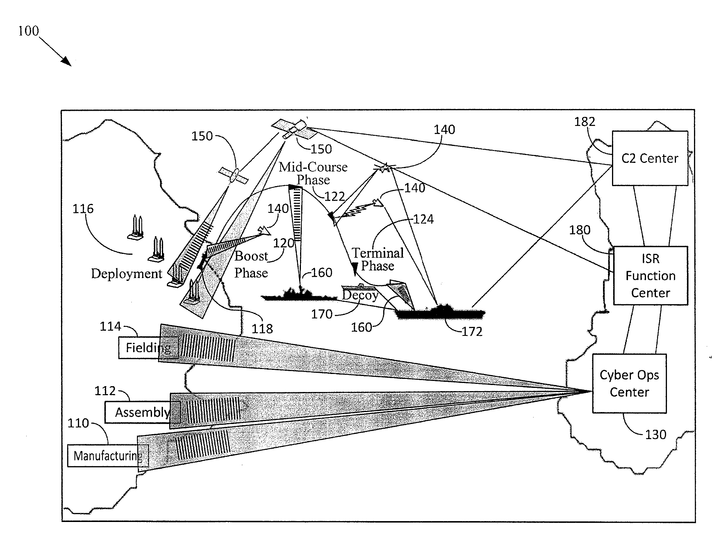
[0049]FIG. 1 illustrates a notional layered AMD operational view 100 according to an embodiment. In FIG. 1, enemy manufacturing 110 and assembly areas 112 for producing missiles that may be considered a threat. Once manufacturing 110 and assembly 112 are completed, missiles are moved to a fielding area 114 where they are prepared for deployment areas 116. Once a missile 118 is launched, the missile 118 enters a boost phase 120 and then a mid-course phase 122. Next, the missile 118 enters a terminal phase 124 where the missile 118 attempts to disable or destroy a target. Defending against the missile 118 may be desirable, especially if the target has a high value.

[0050]Various ...


PUM


Abstract

A method for accurately determining whether a response tool will be effective for responding to a given enemy threat object. Embodiments described herein provide a method and system for responding to a threat object, for example, negating missile threats. Embodiments may include validating effectiveness of a response to the threat object. Other embodiments may include verifying the continued effectiveness of a response to the threat object. Further embodiments may include providing feedback to re-perform the method for responding to the threat object. The system may include a mathematical method, and associated algorithms, to assess, in an automated fashion, the performance of non-kinetic techniques with respect to negating the threat object.

Description

RELATED APPLICATIONS[0001]This application claims the benefit of U.S. Provisional Application No. 61 / 929,252 filed Jan. 20, 2014, which is hereby incorporated herein by reference in its entirety.[0002]Also, this application is related to two commonly-assigned concurrently-filed applications, “Integrated Digital Weapons Factory and Digital Operations Center for Producing, Deploying, Assessing, and Managing Digital Defects” (Attorney Docket No. RAYTP0650USA), which is hereby incorporated herein by reference in its entirety; and “Process of Probabilistic Multi-Source Multi-INT Fusion Benefit Analysis” (Attorney Docket No. RAYTP0651 USA), which is hereby incorporated herein by reference in its entirety.BACKGROUND[0003]Continued proliferation of long range missiles and the fielding of sophisticated threats, such as the maneuvering re-entry vehicle, pose challenges for the fielded Ballistic Missile Defense System (BMDS) weapon systems. However, as missile defense has evolved from World Wa...

Claims


Application Information

Patent Timeline
Patent Type & Authority Applications(United States)
IPC IPC(8): G06N5/04G06N7/00G06N99/00
CPCG06N5/04G06N7/005G06N99/005F41H11/00
Inventor HERSHEY, PAUL C.DEHNERT, ROBERT E.WILLIAMS, JOHN J.WISNIEWSKI, DAVID J.
Owner RAYTHEON CO
Learn More