Method and System for Determining 3D Object Poses and Landmark Points using Surface Patches

a technology of surface patches and landmark points, applied in the field of computer vision, can solve problems such as reducing accuracy

Active Publication Date: 2016-09-01
MITSUBISHI ELECTRIC RES LAB INC
View PDF8 Cites 44 Cited by
  • Summary
  • Abstract
  • Description
  • Claims
  • Application Information

AI Technical Summary

Benefits of technology

[0015]Each correspondence yields an estimate of the pose of the object, which includes the 3D rotation and 3D translation, and the 3D locations of object landmark points. Although eac...

Problems solved by technology

In prior-art models that work with noisy sensors, the training data must be ac...

Method used


Image

  • Method and System for Determining 3D Object Poses and Landmark Points using Surface Patches
  • Method and System for Determining 3D Object Poses and Landmark Points using Surface Patches
  • Method and System for Determining 3D Object Poses and Landmark Points using Surface Patches

Examples


Embodiment Construction

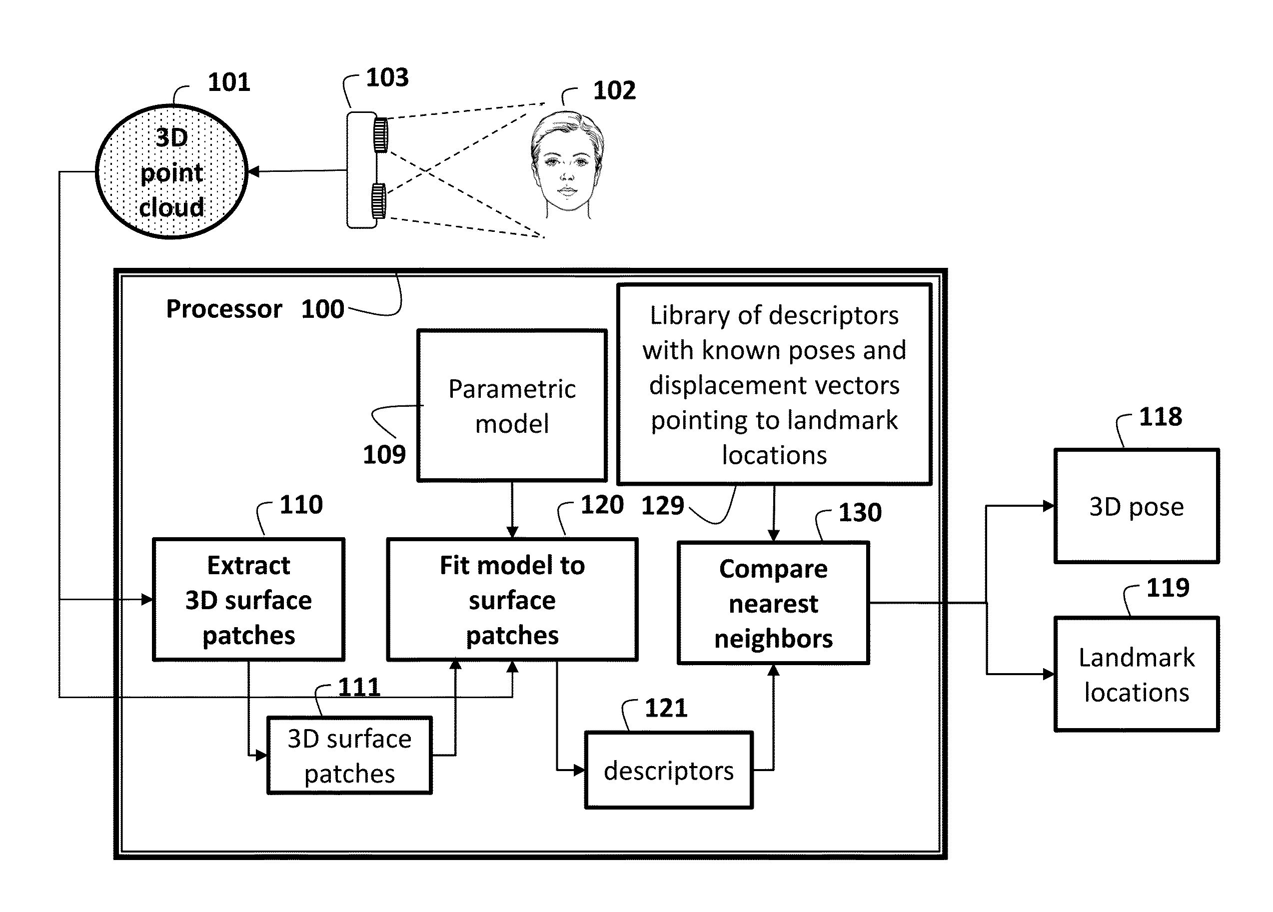
[0029]System and Method Overview

[0030]As shown in FIG. 1, embodiments of the invention provide a method and system for automatically determining a 3D pose 118 and 3D locations 119 of, e.g., facial landmarks of a head 102. A 3D point cloud 101 is obtained. The means for obtaining can be, e.g., by computing the 3D point cloud from a depth image acquired by a depth sensor 103. From the 3D point cloud, the method extracts 110 3D surface patches 111. A parametric model 109 is fitted 120 to each 3D surface patch. Parameters used to fit the surface patch are used as a descriptor for the patch, e.g., in the form of a feature vector. The information that has been extracted from the observed 3D point cloud is thus contained in a set of descriptors 121 of all of the extracted surface patches 111. An approximate nearest neighbor algorithm is used to determine a set of correspondences between the set of descriptors of the patches extracted from the 3D point cloud and descriptors of similar surfa...


PUM


Abstract

A method and system determine a three-dimensional (3D) pose of an object and 3D locations of landmark points of the object by first obtaining a 3D point cloud of the object. 3D surface patches are extracted from the 3D point cloud, and a parametric model is fitted to each 3D surface patch to determine a set of descriptors. A set of correspondences between the set of descriptors and a set of descriptors of patches extracted from 3D point clouds of objects from the same object class with known 3D poses and known 3D locations of landmark points is determined. Then, the 3D pose of the object and 3D locations of the landmark points of the object are estimated from the set of correspondences.

Description

FIELD OF THE INVENTION[0001]This invention is generally related to computer vision, particularly to determining the 3D pose of objects and 3D locations of landmark points of objects, and more particularly to determining 3D head poses and 3D locations of facial landmarks.BACKGROUND OF THE INVENTION[0002]A number of computer vision application require the automatic determination of the three-dimensional (3D) pose (3D rotation angles and 3D translation) of an object, as well as the 3D locations of landmark points on the object, from a 3D point cloud. In particular, some applications require the 3D pose of a human head, as well as the 3D locations of facial landmarks, such as centroids of the eyes, from a 3D point cloud. The 3D point cloud is typically constructed from a depth image acquired by a depth sensor, such as a Microsoft Kinect™, a Creative Senz3D™ sensor, or a stereo camera. The 3D point cloud can also be generated synthetically using a 3D model of the object, or the 3D point ...

Claims


Application Information

Patent Timeline
IPC IPC(8): G06T7/00G06K9/46G06K9/00G06T5/10G06V10/764
CPCG06T7/0046G06T7/0075G06T2207/10028G06K9/4604G06K9/00221G06T5/10G06T2207/30201G06T7/75G06V40/165G06V10/454G06V10/82G06V10/764G06V40/16G06F18/24133
Inventor JONES, MICHAEL J.MARKS, TIMPAPAZOV, CHAVDAR
Owner MITSUBISHI ELECTRIC RES LAB INC
Why Eureka
Try Eureka