Modular Vehicle Architecture

a module-based vehicle technology, applied in the field of mechanical engineering, can solve the problems of reducing payload capacity, not being easy to maintain, and compromising visibility, and achieve the effect of improving maintainability and manufacturing process

Inactive Publication Date: 2016-09-08
THALES AUSTRALIA
View PDF0 Cites 38 Cited by
  • Summary
  • Abstract
  • Description
  • Claims
  • Application Information

AI Technical Summary

Benefits of technology

[0022]In preferred embodiments one or more connections between the capsule and the at least one sub-frame comprises a fastening between a hull plate of the capsule and a sub-frame flange of the sub-frame. The fastening preferably comprises one or a combination of a bolt and a dowel where the dowel is for locating the sub frame assembly during its assembly and the bolt is arranged for tightening upon locating the sub frame assembly such that fatigue loads on the connection are minimised and the dowel is capable of dissipating shearing loads.
[0080]In protected vehicle applications, enhanced level of blast protection as no heavy components are located below the capsule.

Problems solved by technology

The vehicle structure of WO 2010 / 044944, along with other example architectures of a similar box section design, can be relatively heavy with the frame itself occupying a lot of space, prone to corrosion and moisture traps where moisture pools or comes to rest within and upon the chassis structure and may not be easy to maintain as maintenance access through the sub-frame is difficult.
Generally speaking, having engine and drive components situated in a rear sub-frame as such may reduce payload capacity.
In this respect, whilst some payload may be able to be placed at the front of the vehicle but cannot be substantial or of any significant height as visibility would be compromised as a result.
Another example is the so-called truck chassis with a C section and this design is considered relatively weak with torsion applied to it.
Further, it can't easily be replaced if damaged.
In summary, box section sub-frame designs are generally heavier and more prone to moisture and corrosion and are less easy to maintain.
Non modular vehicles (full chassis in one piece) are susceptible to be heavier as the whole vehicle is protected not an isolated capsule.
Also it is noted that a truck chassis with a C section is a design that is weak with torsion and can't be easily replaced if damaged.
In current vehicle designs both front and rear bulkheads are very difficult or impossible to be up-armored from A-kit armor known in the military for lower level threats to B-Kit armor that is commonly installed / bolted on for upper level threats that occur during combat missions.
As shown in WO 2010 / 044944 commonly this has led to separating drive components to be situated both in front and to the rear of the cab, however, this can lead to payload capacity being compromised.
Further to this, in accommodating additional drive and vehicle components that were hitherto residing at or within the cab, the front and / or rear portions of the vehicle design under conventional frame design may restrict space for vehicle components.

Method used


Image

  • Modular Vehicle Architecture
  • Modular Vehicle Architecture
  • Modular Vehicle Architecture

Examples


Embodiment Construction

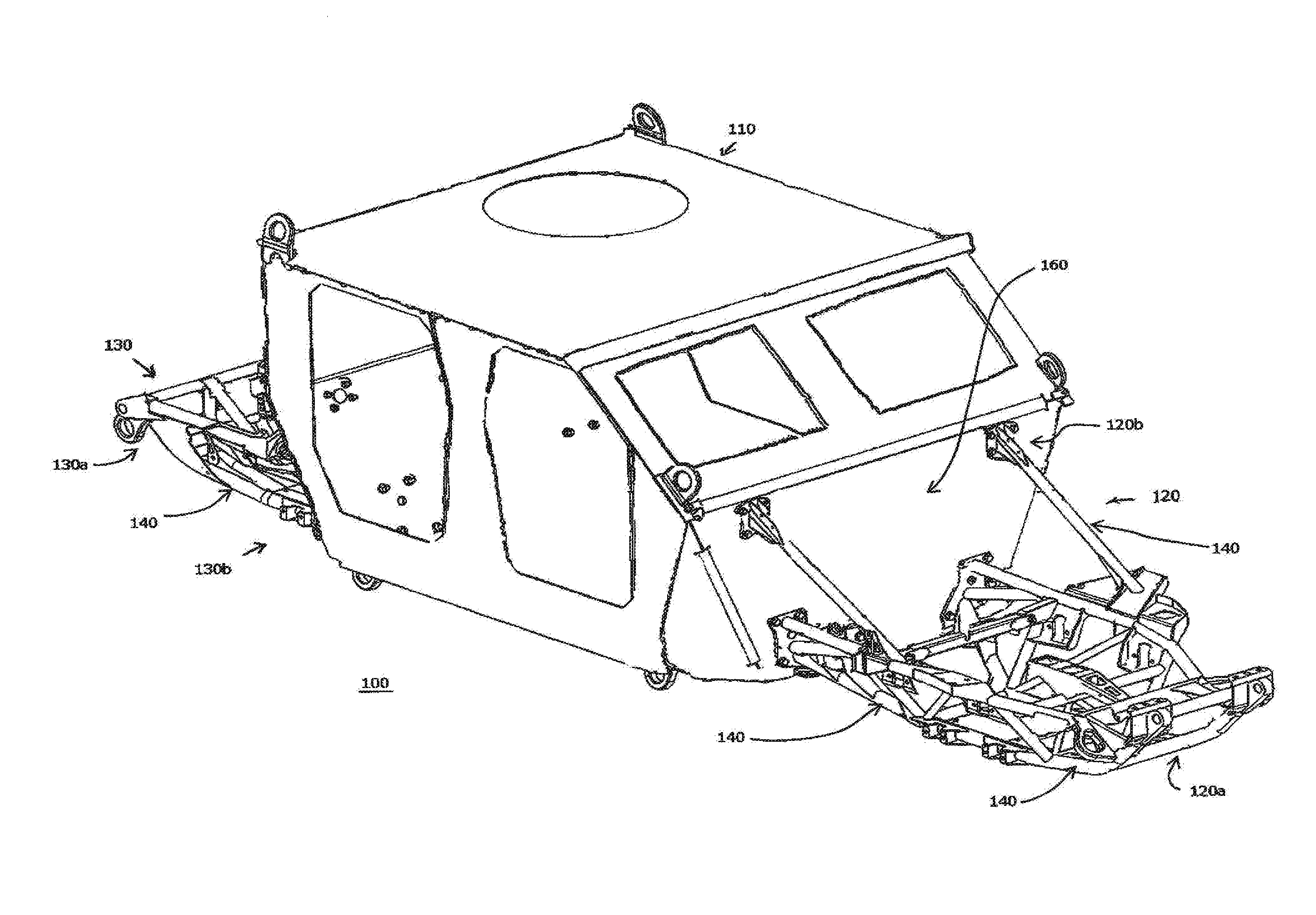
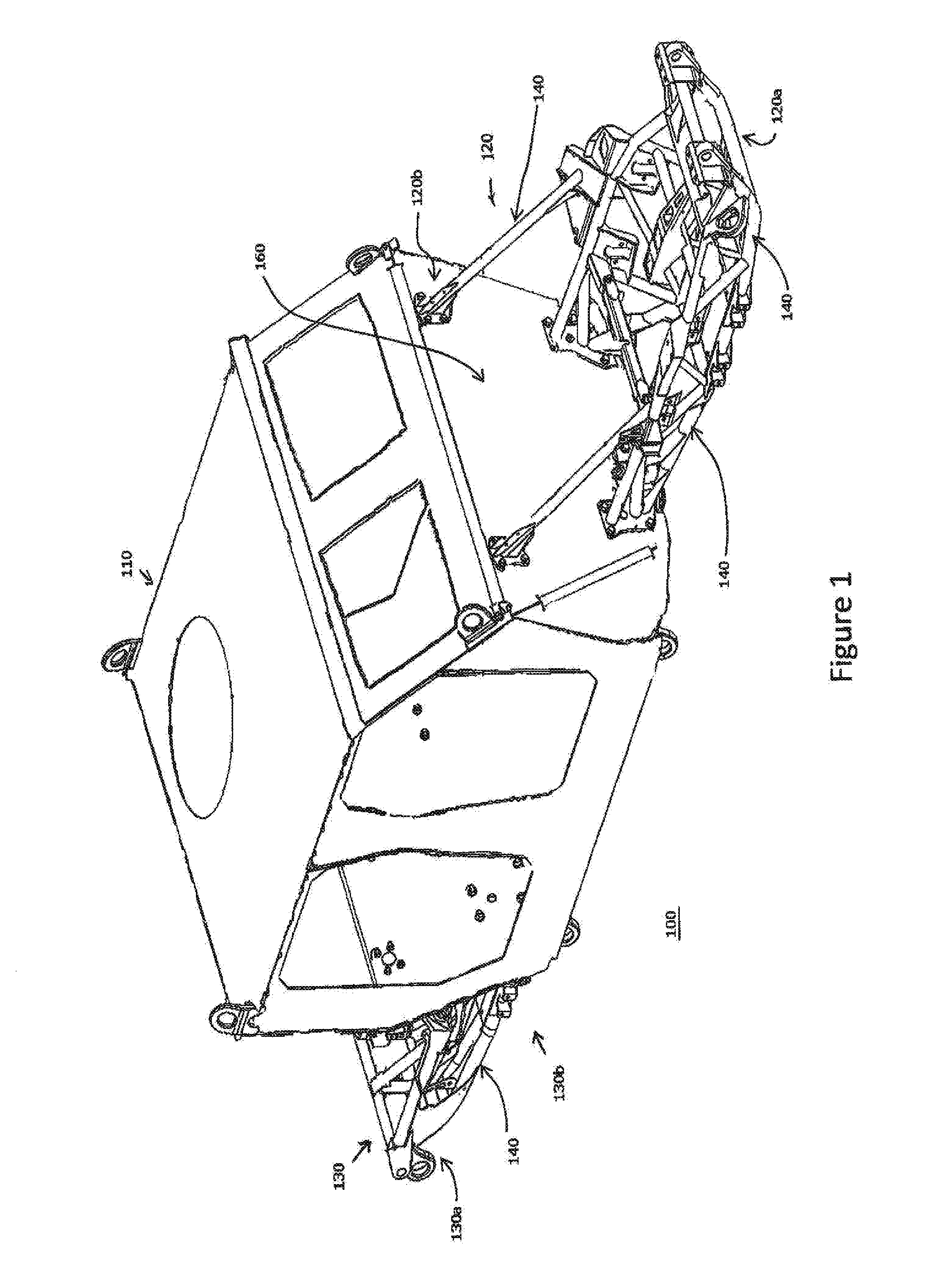
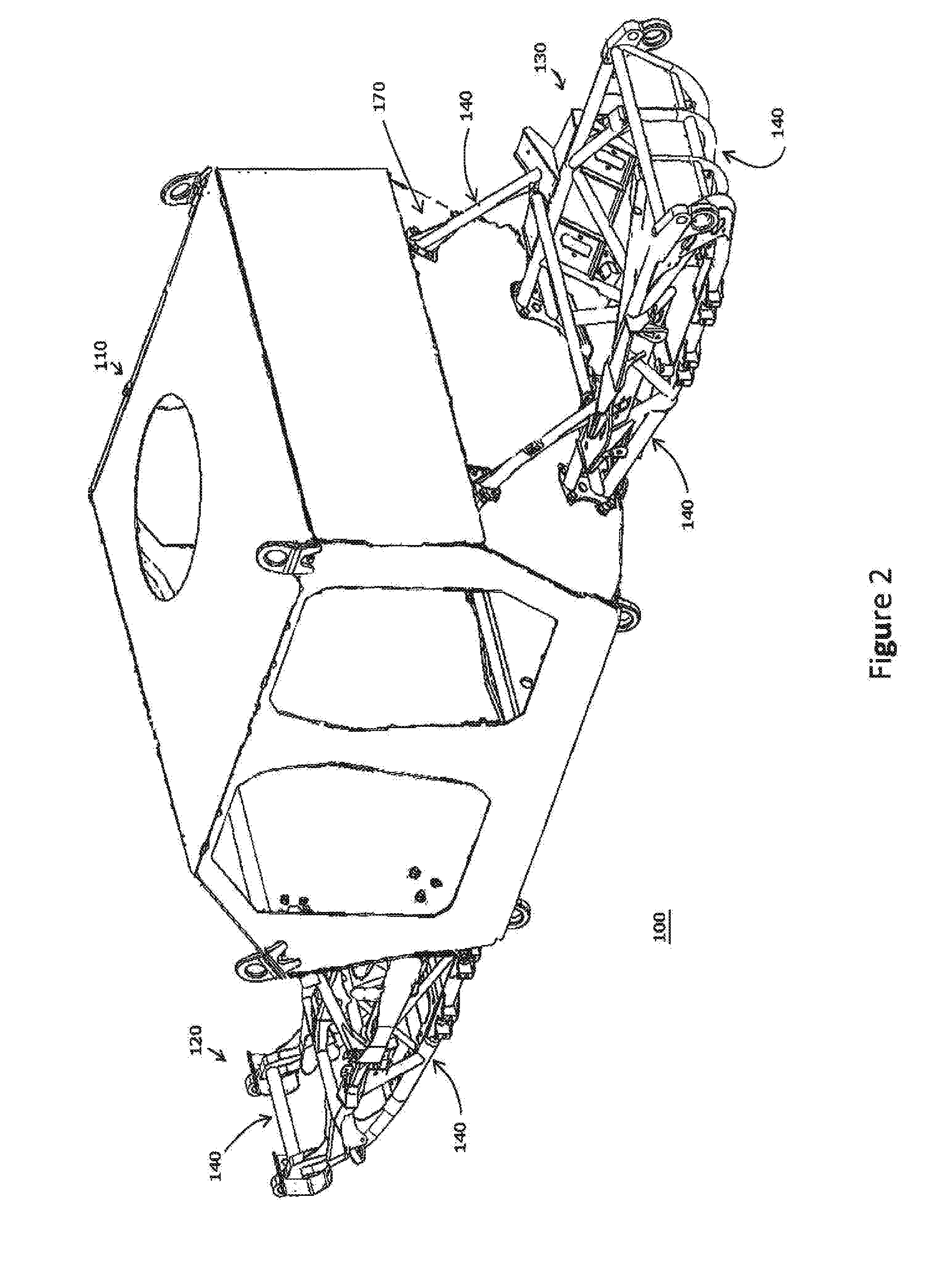
[0089]Referring to FIGS. 1 & 2, a protected military vehicle 100 comprising a protected capsule module 110, a front sub-frame module 120 and a rear sub-frame module 130 in accordance with one embodiment of the present invention is shown. The front sub-frame module 120 comprises a distal end 120a and a proximal end 120b, at which are located connections 120c (FIGS. 4 & 6) with the protected capsule module 110. Proximal end 120b of front sub-frame module 120 may be attached to protected capsule module 110 of the vehicle 100 utilising at least one of the connections 120c shown in better detail in FIGS. 5 and 6, significantly increasing the efficiency of assembling vehicle 100. Rear sub-frame module 130 comprises a distal end 130a and a proximal end 130b. Proximal end 130b of rear sub-frame module 130 may be attached to capsule module 110 of the vehicle 100 utilising the connections 130c (FIG. 6) shown in better detail in FIG. 5 or 6 significantly increasing the efficiency of assembling...


PUM


Abstract

The present invention relates to the field of mechanical engineering, in particular, vehicles. In one form, the invention relates to military or defence industry protected (armoured) vehicles with a modular vehicle architecture comprising: a capsule adapted for accommodating at least one occupant; at least one sub-frame detachably operatively connected to the capsule; wherein at least the sub-frame construction comprises members of tubular structure having a cross section corresponding to a conic section.

Description

RELATED APPLICATIONS[0001]This application claims priority to Australian Provisional Patent Application No. 2013904207 in the name of Thales Australia Limited, which was filed on 31 Oct. 2013, entitled “Modular Vehicle Architecture” and, to Australian Innovation Patent Application No. 2013101433 in the name of Thales Australia Limited, which was filed on 31 Oct. 2013, entitled “Modular Vehicle Architecture” and the specifications thereof are incorporated herein by reference in their entirety and for all purposes.FIELD OF INVENTION[0002]The present invention relates to the field of mechanical engineering and, in particular it relates to vehicles. In one form, the invention relates to military or defence industry protected (armoured) vehicles. The invention may also be applicable generally to land vehicles, for example, vehicles used in mining, fire fighting, police, emergency services, automotive industry and agriculture. It will be convenient to hereinafter describe the invention in...

Claims


Application Information

Patent Timeline
Patent Type & Authority Applications(United States)
IPC IPC(8): B62D63/02B62D25/08B62D21/11F41H7/04
CPCB62D63/025F41H7/048B62D25/082B60Y2200/116B60Y2200/22B60Y2200/24B60Y2200/41B62D21/11
Inventor MACKENZIE, CRAIG LACHLANHARRIS, GREG
Owner THALES AUSTRALIA
Why Eureka
Try Eureka