Spherical ball bearing housing

a technology of ball bearings and housings, which is applied in the direction of bearing units, machines/engines, light and heating apparatus, etc., can solve the problems of gas turbine engine excess bulk, fuel supply manifolds that may complicate the assembly process of combustor, and myriad of problems

Active Publication Date: 2016-09-08
RAYTHEON TECH CORP
View PDF4 Cites 3 Cited by
  • Summary
  • Abstract
  • Description
  • Claims
  • Application Information

AI Technical Summary

Problems solved by technology

In such examples, the fuel supply manifolds may complicate the assembly process for the combustor.
Further, such fuel supply manifolds may be difficult to manufacture and are may add unwanted, excess bulk to the gas turbine engine.
However, mounting a fuel supply manifold to the exterior of the diffuser case causes a myriad of issues during production and assembly...

Method used


Image

  • Spherical ball bearing housing
  • Spherical ball bearing housing
  • Spherical ball bearing housing

Examples


Embodiment Construction

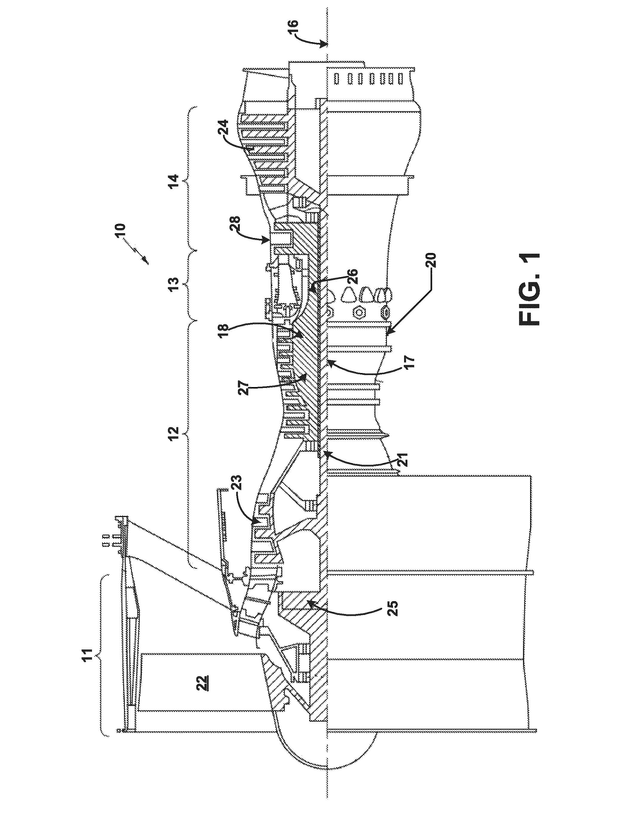
[0036]Referring to the drawings, and with specific reference to FIG. 1, a gas turbine engine constructed in accordance with the present disclosure is generally referred to by reference numeral 10. Such a gas turbine engine 10 can be used for any number of different applications including, but not limited to, generation of aircraft thrust and land-based power. Moreover, it is to be understood that the sectional view provided in FIG. 1 is included simply to provide a basic understanding of the various sections in a gas turbine engine, and not to limit the invention thereto. The present disclosure extends to all types of gas turbine engines used in all types of applications.

[0037]The gas turbine engine 10 may have a fan section 11, the fan section 11 drawing in ambient air and directing the ambient air to a compressor section 12. The incoming air is greatly compressed by the compressor section 12 and directed to a combustor 13 where it is mixed with fuel and combusted. The products of ...


PUM


Abstract

A fuel supply manifold of a gas turbine engine, a method for assembling a fuel supply manifold for a gas turbine engine, and a gas turbine engine are disclosed. The fuel supply manifold for the gas turbine engine man include a plurality of fuel supply tubes, a fitting connecting at least two members of the plurality of fuel supply tubes, a bracket attached to the fitting, a bearing housing having a ball bearing, a bushing attached to a diffuser case of the gas turbine engine, wherein the bushing is surrounded by the ball bearing, and a removable fastener to connect the bearing housing to the bracket.

Description

TECHNICAL FIELD OF THE DISCLOSURE[0001]The present disclosure relates to gas turbine engines and, more particularly, to a fuel manifold system for a gas turbine engine.BACKGROUND OF THE DISCLOSURE[0002]Gas turbine engines, such as those used to power modern commercial and military aircraft, include a combustor to burn a hydrocarbon fuel in the presence of pressurized air received from a compressor section upstream of the combustor. A fuel supply system may be mounted around the combustor, which is typically annular in shape, to provide the hydrocarbon fuel to a plurality of fuel injectors associated with the combustor of the gas turbine engine.[0003]Such a fuel supply system may be attached to one or more fuel injectors which axially project the fuel into the combustor. The fuel injectors may be connected to one or more fuel supply manifolds which deliver the fuel to the fuel injectors. The fuel supply system may be an assembly of formed tubes which are cut, measured, assembled and ...

Claims


Application Information

Patent Timeline
IPC IPC(8): F02C7/22F02C7/06F23R3/28F02C3/04F16C35/06F23R3/10
CPCF05D2240/54F02C7/222F16C35/06F23R3/10F05D2240/90F02C3/04F02C7/06F05D2220/32F05D2240/35F23R3/28F02C7/22
Inventor SHEIL, ROBERT F.AVIS, THOMAS BRUCETU, PETER
Owner RAYTHEON TECH CORP
Why Eureka
Try Eureka