Measurement apparatus and measurement method

a measurement apparatus and measurement method technology, applied in the direction of image analysis, image enhancement, picture signal generators, etc., can solve the problems of deteriorating accuracy of measured shape information, inability to perform detection itself, and difficulty in measuring, so as to achieve accurate measurement of surface shape information

Inactive Publication Date: 2016-09-08
CANON KK
View PDF11 Cites 6 Cited by
  • Summary
  • Abstract
  • Description
  • Claims
  • Application Information

AI Technical Summary

Benefits of technology

[0010]The present invention provides a measurement apparatus w

Problems solved by technology

When measuring a surface to be measured which moves at high speed, it is difficult to perform the measurement by using the multi-shot scheme, and hence the single-shot scheme is used for the measurement.
These influences may cause errors in the detection of dots and lines or may lead to inability to perform detection itself.
As a consequence, the accuracy of measured shape information deteriorates.
This, in particular, makes it difficult to reconstruct coordinate information on a deep color s

Method used


Image

  • Measurement apparatus and measurement method
  • Measurement apparatus and measurement method
  • Measurement apparatus and measurement method

Examples


first embodiment

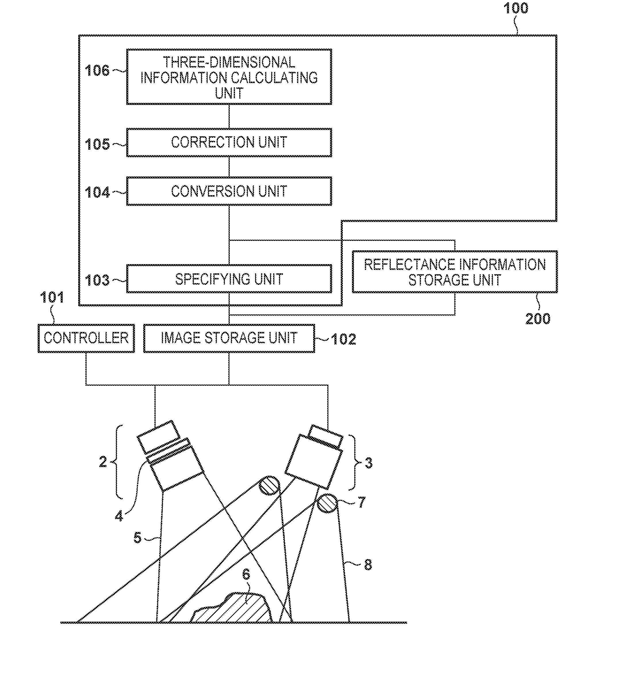
[0025]FIG. 1 shows a measurement apparatus which measures, for example, the three-dimensional shape of a surface to be measured according to the first embodiment. This measurement apparatus, like a conventional measurement apparatus, includes a first illumination unit 2 which illuminates a surface 6 to be measured (target object) with first light having a first wavelength with a slit shape and an image sensing unit 3 which senses an image of the surface 6. The first illumination unit 2 includes a light source which emits light having the first wavelength, a generation unit 4 which generates first light (pattern light) having a light intensity distribution with a pattern shape, and a projection optical system such as a lens. The image sensing unit 3 includes a CCD or CMOS (not shown) and an imaging optical system such as a lens. A controller 101 controls the first illumination unit 2 for the first light and the image sensing unit 3.

[0026]The first illumination unit 2 illuminates the ...

second embodiment

[0037]The second embodiment will be described next. An apparatus arrangement and method used for the calculation of a three-dimensional shape and the correction of the first image according to the second embodiment are the same as those used in the first embodiment. In the second embodiment, however, no reflectance information is input to a reflectance information storage unit 200 in advance. Instead of this, the second embodiment includes an apparatus arrangement for obtaining reflectance information. In addition to the apparatus arrangement described in the first embodiment, a measurement apparatus according to the second embodiment shown in FIG. 10 includes another illumination unit (third illumination unit) 9 which illuminates an illumination region having a wide surface 6 to be measured with light having a wavelength λ1. The third illumination unit 9 emits third light 10 having the same wavelength λ1 as that of first light 5. Note that an example of the form of the third illumi...

third embodiment

[0041]The third embodiment will be described next. Like the second embodiment, the third embodiment has an apparatus arrangement and process for obtaining the reflectance information of a surface 6 to be measured, but differs from the second embodiment in a method of obtaining reflectance information. A measurement apparatus according to the third embodiment shown in FIG. 11 includes a switching mechanism 11 which switches a generation unit 4 in the apparatus arrangement described in the first embodiment between a position on an optical path and a position outside the optical path. The switching mechanism 11 is, for example, a liquid crystal shutter.

[0042]In the third embodiment, a second illumination unit 7 emits second light 8 having a wavelength λ2 at the same time that a light source emits third light 12 having a wavelength λ1 under the control of the switching mechanism 11. This embodiment is configured to irradiate a wide illumination region of the surface 6 with light beams h...


PUM


Abstract

A measurement apparatus includes: a first illumination unit configured to illuminate the surface with first light having a first wavelength having a light intensity distribution in a pattern shape; a second illumination unit configured to illuminate, with second light having a second wavelength, a region wider than an illumination region illuminated with the first light; an image sensing unit configured to sense an image of the surface; and a processor. The processor is configured to obtain a first image of the first wavelength and a second image of the second wavelength of the surface unit while illuminating the surface by using the first and second illumination units, correct the first image based on the second image, and obtain information of a shape of the surface by using the corrected first image.

Description

BACKGROUND OF THE INVENTION[0001]1. Field of the Invention[0002]The present invention relates to a measurement apparatus and measurement method which measure the shape of a surface to be measured.[0003]2. Description of the Related Art[0004]An optical measurement apparatus is one of techniques of evaluating the shape of a surface to be measured. Optical measurement apparatuses based on various types of schemes are available. A scheme called a pattern projection method is one of these schemes. This scheme is designed to measure the shape of a surface to be measured (target object) by performing image sensing by projecting a predetermined projection pattern on the surface and calculating distance information at each pixel position from the principle of triangulation. Pattern projection methods are further classified into a plurality of schemes according to pattern projection methods, which include a multi-shot scheme of projecting a plurality of patterns, such as a phase shift method ...

Claims


Application Information

Patent Timeline
IPC IPC(8): G06T7/00G06T5/50G01B11/25H04N9/04
CPCG06T7/0018H04N9/04G06T2207/10152G01B11/2513G06T2207/10024G06T5/50G06T7/586H04N23/56H04N23/10
Inventor KITAMURA, TSUYOSHI
Owner CANON KK
Why Eureka
Try Eureka