Aperture segmentation of a cylindrical feed antenna

a cylindrical feed antenna and segmentation technology, applied in the field of antennas, can solve problems such as inability to be feasibl

Active Publication Date: 2016-09-08
KYMETA
View PDF1 Cites 39 Cited by
  • Summary
  • Abstract
  • Description
  • Claims
  • Application Information

AI Technical Summary

Problems solved by technology

However, using rows and columns of conductors may be useful in antenna arrays that have antenna elements that...

Method used


Image

  • Aperture segmentation of a cylindrical feed antenna
  • Aperture segmentation of a cylindrical feed antenna
  • Aperture segmentation of a cylindrical feed antenna

Examples


Embodiment Construction

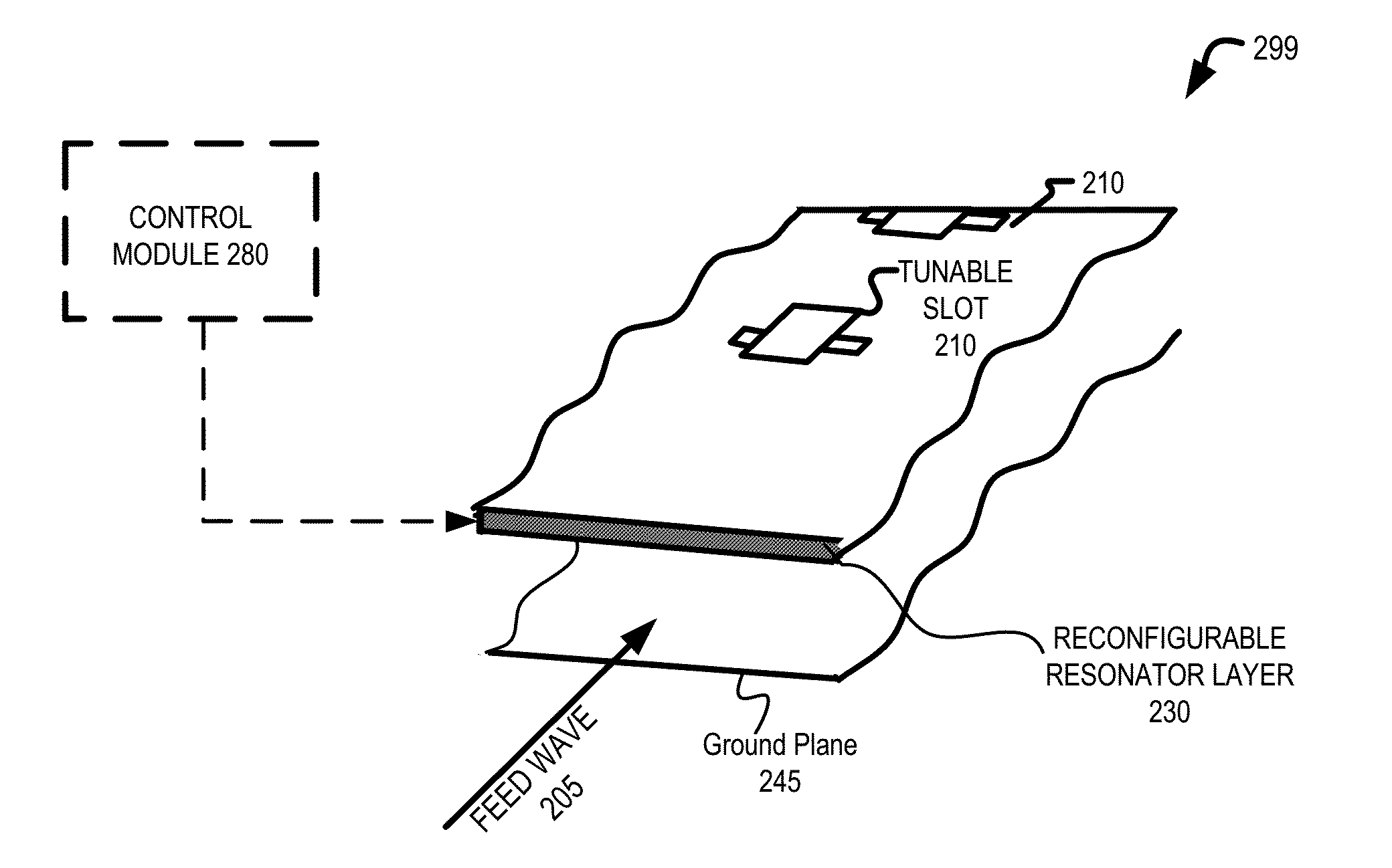
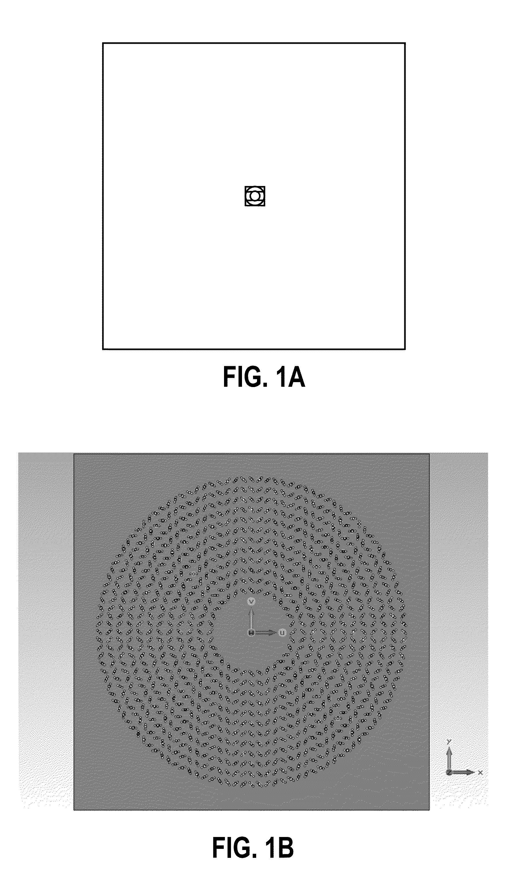
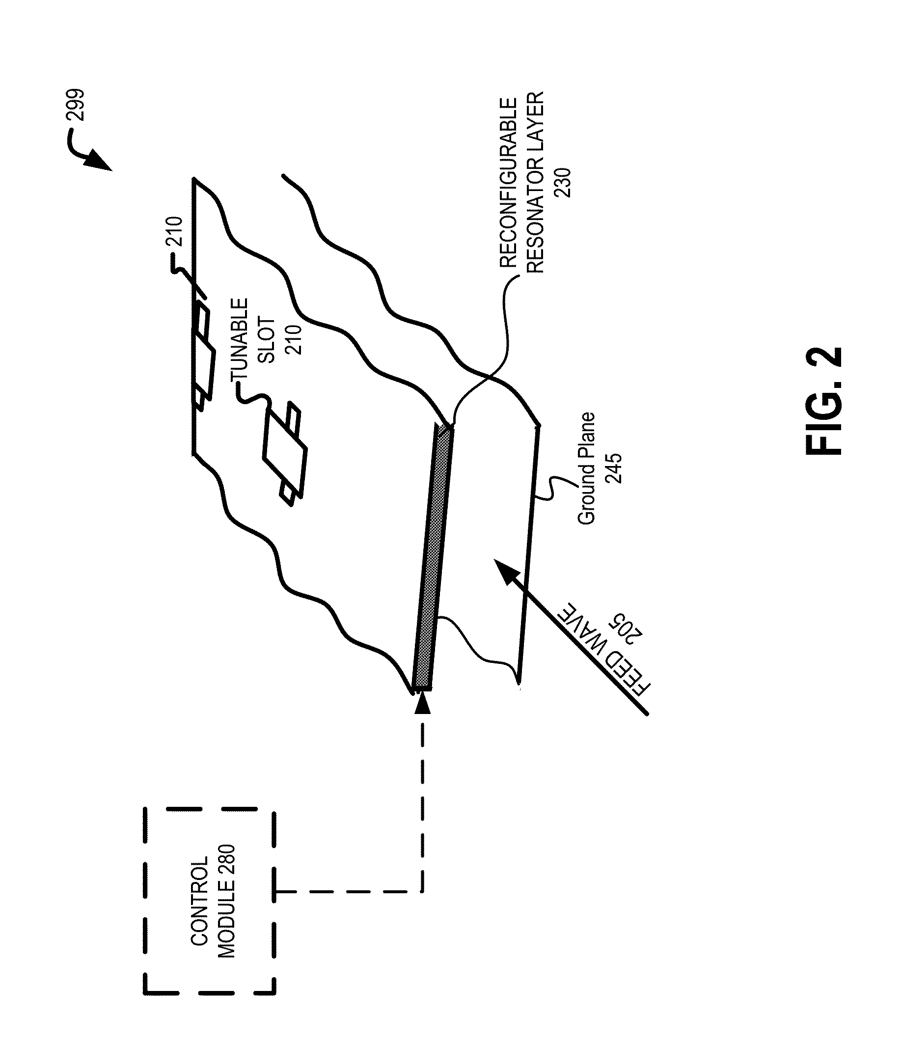
[0031]Embodiments of flat panel antennas are disclosed. The flat panel antennas include one or more arrays of antenna elements on an antenna aperture. In one embodiment, the antenna elements comprise liquid crystal cells. In one embodiment, the flat panel antenna is a cylindrically fed antenna that includes matrix drive circuitry to uniquely address and drive each of the antenna elements that are not placed in rows and columns. In one embodiment, the elements are placed in rings.

[0032]In one embodiment, the antenna aperture having the one or more arrays of antenna elements is comprised of multiple segments coupled together. When coupled together, the combination of the segments form closed concentric rings of antenna elements. In one embodiment, the concentric rings are concentric with respect to the antenna feed.

[0033]In the following description, numerous details are set forth to provide a more thorough explanation of the present invention. It will be apparent, however, to one ski...


PUM


Abstract

A method and apparatus for aperture segmentation are disclosed. In one embodiment, the antenna comprises an antenna feed to input a cylindrical feed wave and a physical antenna aperture coupled to the antenna feed and comprising a plurality of segments having antenna elements that form a plurality of closed concentric rings of antenna elements when combined, where the plurality of concentric rings are concentric with respect to the antenna feed.

Description

PRIORITY[0001]The present patent application claims priority to and incorporates by reference the corresponding provisional patent application Ser. Nos. 62 / 128,894, titled, “Cell Placement with Predefined Matrix Drive Circuitry for Cylindrical Feed,” filed on Mar. 5, 2015; 62 / 128,896, titled “Vortex Matrix Drive Lattice for Cylindrical Feed Antennas,” filed on Mar. 5, 2015; 62 / 136,356, titled “Aperture Segmentation of a Cylindrical Feed Antenna,” filed on Mar. 20, 2015; and 62 / 153,394, titled “A Metamaterial Antenna System for Communications Satellite Earth Stations”, filed Apr. 27, 2015.RELATED APPLICATIONS[0002]This application is related to the co-pending application entitled “Antenna Element Placement for a Cylindrical Feed Antenna”, concurrently filed on Mar. 3, 2016, U.S. patent application Ser. No. ______, assigned to the corporate assignee of the present invention.FIELD OF THE INVENTION[0003]Embodiments of the present invention relate to the field of antennas; more particula...

Claims


Application Information

Patent Timeline
IPC IPC(8): H01Q3/24H01Q21/06H01Q21/00
CPCH01Q3/24H01Q21/064H01Q21/0031H01P1/18H01Q3/34H01Q21/0012H01Q21/0025H01Q21/0087H01Q21/065
Inventor SAZEGAR, MOHSENKUNDTZ, NATHANLINN, STEVE
Owner KYMETA
Why Eureka
Try Eureka