Joining device and joining method

a technology of joining device and resin member, which is applied in the direction of resistive welding apparatus, metal-working apparatus, welding electric supply, etc., can solve the problems of resin member cracks, difficult to match the screw position, and difficult to maintain waterproofness and airtightness

Active Publication Date: 2016-09-08
NEWFREY
View PDF49 Cites 11 Cited by
  • Summary
  • Abstract
  • Description
  • Claims
  • Application Information

AI Technical Summary

Benefits of technology

[0017]The object of the present invention is to provide a joining device and joining method for a resin member and a metal member with which, when joining a resin member and a...

Problems solved by technology

However, fastening by screw requires formation in advance of screw holes in the resin member and metal member, which is laborious.
It is also difficult to match the screw position to the screw holes in the resin member and metal member for screwing in.
The presence of the screw hole makes it difficult to maintain waterproofness and airtightness.
The problem arises, however, that cracks can easily form in the resin member during riveting if the resin member is rigid.
It is also easy for gaps to form between the rivet and the resin member and metal member, making it difficult to maintain waterproofness and airtightness.
In adhesion, however, the application of the adhesive is laborious, and processing such as heating or applying pressure and clamping are required to cure the adhesive, thus requiring time.
In JP S.61-269986, however, ele...

Method used


Image

  • Joining device and joining method
  • Joining device and joining method
  • Joining device and joining method

Examples


first embodiment

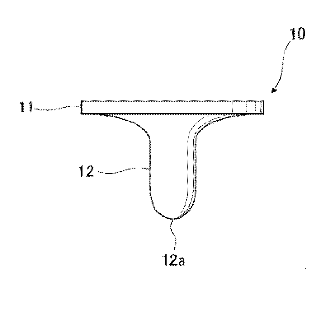
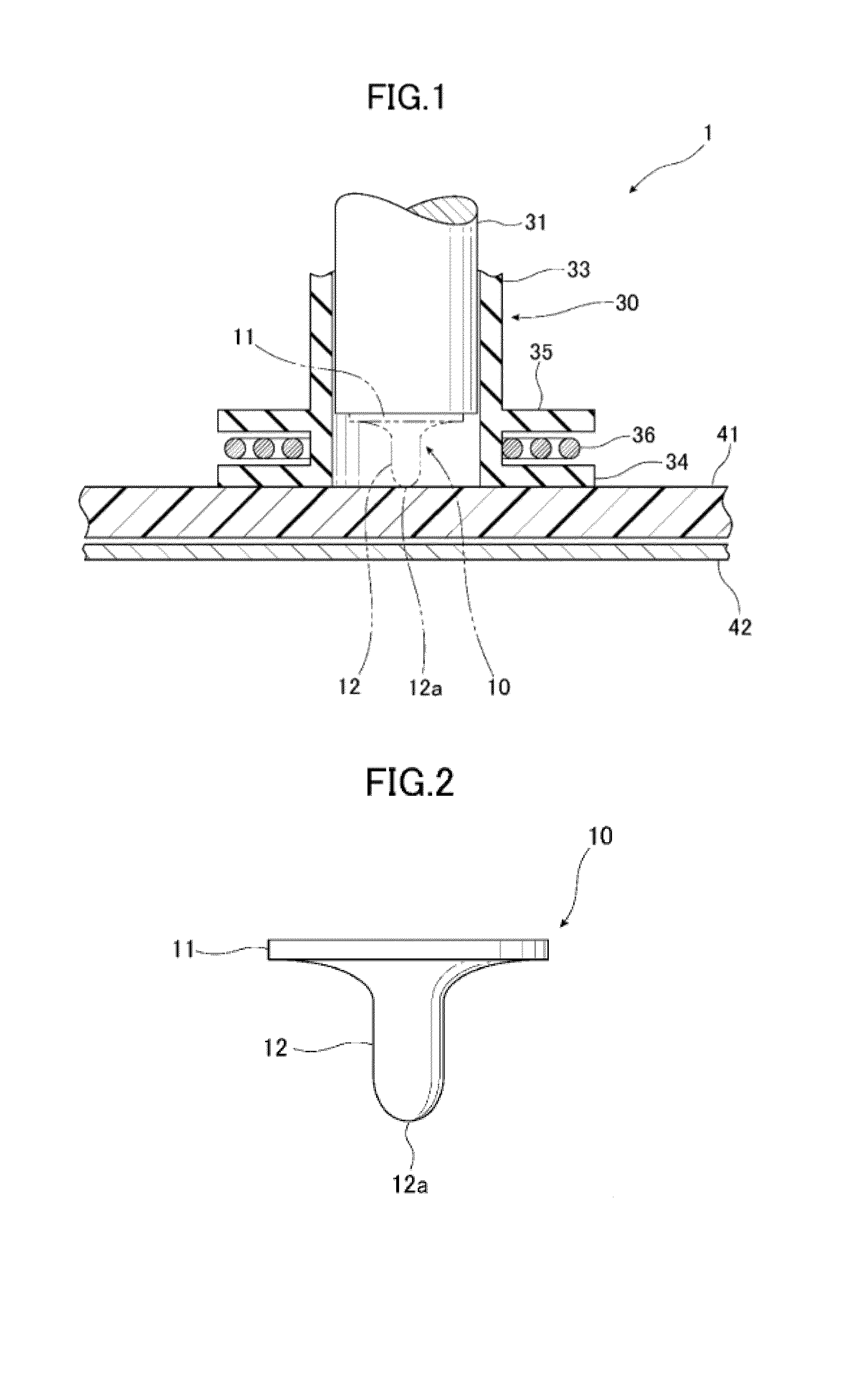
[0065]FIG. 1 is a cross section of the welding head portion, which is part of the joining device 1 of the present invention. The joining device 1 laminates the resin member 41 and metal member 42, heats a fastener 10 by high-frequency induction heating, press-fitting the fastener 10 into the resin members 41 as it softens and melts the resin member 41. The resistance of the joining device 1 welds the fastener 10 and the metal member 42 when the tip portion 12a of the fastener 10 contacts the metal member 42, joining the resin member 41 and the metal member 42.

[0066]The welding head comprises a nose piece 30, a high-frequency coil 36 and an electrode punch 31.

[0067]The joining device 1 may also comprise a die to receive the resin member 41 and metal member 42. When using a die, the top surface of the die is a plane for placement of the resin member 41 and metal member 42. Dies are normally made of metal. In an embodiment of the invention, resistance welding is performed under a low a...

second embodiment

[0124]In addition, the joining device 2 of the second embodiment has a chuck 37 on the inside of the nose piece 30 cylindrical portion 33. The chuck 37 is able to hold the fastener 10, separated by an interval from the electrode punch 31.

[0125]We previously explained the case in which the fastener 10 of the first embodiment is used, but it is also possible to use the fasteners 20, 20′ and 20″ of Embodiments 2 through 4 in the joining device 2 of the second embodiment.

[0126]The joining device 2 may also comprise a die to receive the resin member 41 and metal member 42. It is also acceptable that there not be a die. The metal member 42 and resin member 41 for joining are overlapped and affixed in a jig. A lower electrode for resistance welding is connected to the metal member 42.

[0127]A cylindrical nose piece 30 is positioned above the resin member 41, separated from the resin member 41 by an interval. The nose piece 30 comprises a cylindrical portion 33 and a high-frequency induction...


PUM

PropertyMeasurementUnit
Electric potential / voltageaaaaaaaaaa
Frequencyaaaaaaaaaa

Abstract

A joining device for connecting a metal member and a resign member with a metal fastener including a penetrating tip comprises: a cylindrical nosepiece; a high frequency electromagnetic induction coil around the nosepiece; an electrode punch for pressing the fastener into the resign member; a electronic chopper for producing a high frequency current; a high frequency power supply for supplying an induction current to the induction coil; a welding power supply for supplying a welding current between the electrode punch and the metal member; a contact detector for sensing when the fastener tip touches the metal member; and a switching unit for automatically switching from the induction current to the welding current when the contact detector senses that the tip has contacted the metal member.

Description

CROSS-REFERENCE TO RELATED APPLICATIONS[0001]This application is a continuation of PCT Application No. PCT / JP2014 / 068729, filed Jul. 14, 2014 which claims priority from Japanese Patent Application No. 2013-242007, filed on Nov. 22, 2013, the disclosures of which are incorporated herein by reference.BACKGROUND OF THE INVENTION[0002]The present invention pertains to a joining device and joining method for joining a resin member and metal member using a fastener. More particularly, the invention pertains to a joining device and joining method for joining a resin member and metal member whereby a fastener is press-fit from the resin member side, and the fastener and the metal member are welded to join the resin member and the metal member.[0003]Joining methods for joining a resin member and a metal member include screw fastening, rivet punching, adhesion and the like. Screw fastening is accomplished by pre-drilling a swaging hole in a resin member and a metal member, matching the positi...

Claims


Application Information

Patent Timeline
IPC IPC(8): H05B6/10H05B6/36B23K11/25B23K11/30B23K11/02B23K11/24
CPCH05B6/101B23K11/02H05B6/36B23K11/25B23K11/3009B23K11/241B23K11/0026B23K11/0053B23K11/16B23K11/258B23K11/36C21D1/42B29C65/562B29C65/564B29C65/64B29C66/1122B29C66/21B29C66/474B29C66/742B29C66/8322B29C66/71B29C65/46B29C65/7841B29C66/41B29C66/721B29C66/7212Y02P10/25B29K2023/06B29K2023/12B29K2055/02B29K2059/00B29K2069/00B29K2077/00B29K2307/04B29K2309/08B29C66/43
Inventor KONDO, YOSHITERUMIURA, DAISUKE
Owner NEWFREY
Why Eureka
Try Eureka