

Screw for avoiding cracks and burrs
a screw and burr technology, applied in the field of screws, can solve the problems of poor cutting performance, screw b>10/b> not suitable for fastening a hard workpiece, poor cutting performance, etc., and achieve the effect of keeping the workpiece good appearance accordingly and using safely
- Summary
- Abstract
- Description
- Claims
- Application Information
AI Technical Summary
Benefits of technology
Problems solved by technology
Method used
Image

Examples
Embodiment Construction
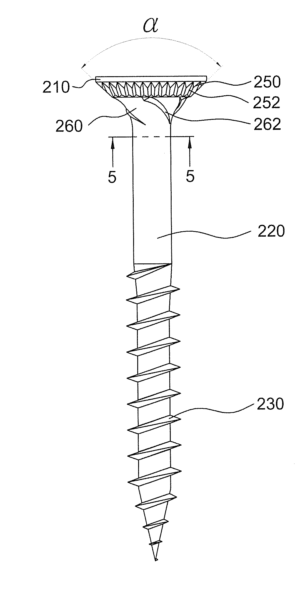
[0067]Reference is made to FIGS. 4a to 28b, which illustrate different screws according to different embodiments of the present disclosure. In these figures, identical reference numerals have been used when designating substantially identical elements that are common to the figures. Each of the screws of the present disclosure includes a flat head 210 and a shank 220. The head 210 is configured to receive a fastening tool. The shank 220 extends downward from the head 210. A thread 230 is formed on the shank 220, which may engage with the workpiece to be fastened, such as soft wood, hard wood, compound material, foamed plastics and synthetic material including recycled plastics, polymer and wood, to provide a resistance to pull-out.
[0068]The head 210 is of tapered shape and has tapered side-surfaces, which include a first side surface 250 and a second side surface 260. The second side surface 260 is located between the first side surface 250 and the shank 220. That is, the second sid...
PUM
 Abstract
Description
Claims
Application Information