Cooking appliance

a technology for cooking appliances and ovens, applied in the field of cooking appliances, can solve the problems of shaft restraint and possible restraint, and achieve the effect of convenient operation

Active Publication Date: 2016-09-15
LG ELECTRONICS INC
View PDF9 Cites 19 Cited by
  • Summary
  • Abstract
  • Description
  • Claims
  • Application Information

AI Technical Summary

Benefits of technology

[0044]Consequently, each of the leaf springs may be formed in a belt shape extending in the circumferential direction. The belt shape may be configured such that the width of belt shape in the circumferential direction is greater than the width of the belt shape in the radial direction. For this reason, the rotation of the knob ring holder may be more easily performed than the movement of the knob ring holder in the radial direction. The rotation of the knob ring holder may be negligible due to the shape of the knob ring holder. In the same manner, the rotation of the knob ring may be negligible due to the shape of the knob ring. That is, symmetry of the knob ring and the knob ring holder in the circumferential direction may be maintained due to the circular shape of the knob ring and the knob ring holder even when the knob ring and the knob ring holder are rotated.
[0045]The movement of the knob ring holder in the radial direction may be more difficult than the rotation of the knob ring holder due to the shape of the leaf springs. As a result, the knob ring holder may be prevented from easily moving in the radial direction when a small force is applied thereto.

Problems solved by technology

Such deformation or positional deviation (eccentricity) of the shaft may cause the restraint of the shaft.
Such restraint may occur due to deformation or eccentricity of the shaft.

Method used


Image

  • Cooking appliance
  • Cooking appliance
  • Cooking appliance

Examples


Embodiment Construction

[0069]Reference will now be made in detail to the preferred embodiments of the present invention, examples of which are illustrated in the accompanying drawings.

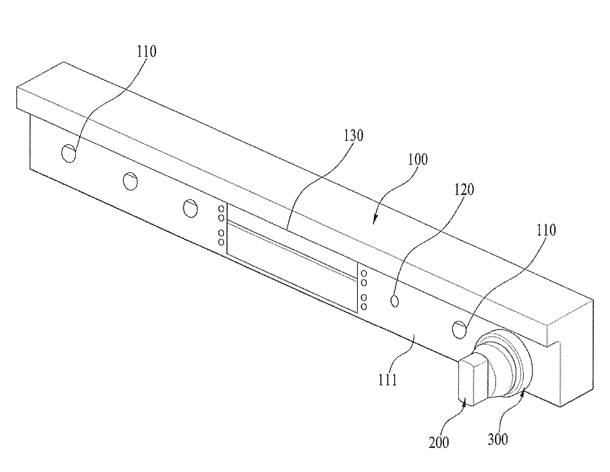
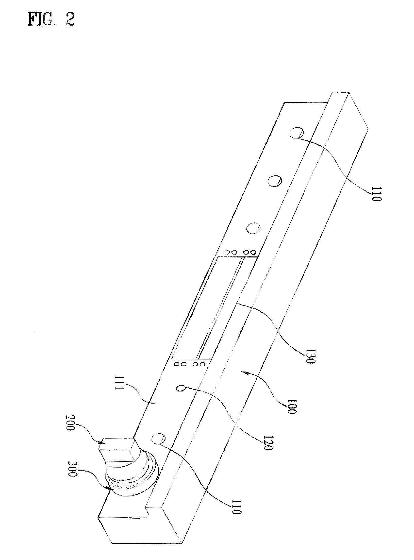
[0070]FIG. 2 is a perspective view showing a panel 100 of a conventional cooking appliance or a panel of a cooking appliance according to an embodiment of the present invention. For the convenience of description, other constructions of the cooking appliance, such as a cabinet and a cooking unit, are omitted from FIG. 2. The cooking appliance according to the embodiment of the present invention may be identical or similar to the conventional cooking appliance in terms of the external appearance of the front part of the panel.

[0071]The panel 100 shown in FIG. 2 may be applied to a gas oven / stove. Similarly, the panel 100 may also be applied to a gas stove or a gas oven. Hereinafter, an embodiment of a gas oven / stove will be described as an example of the cooking appliance. Of course, the panel 100 may also be applied to an el...


PUM


Abstract

A cooking appliance is disclosed. The cooking appliance includes a cabinet defining the external appearance of the cooking appliance, a cooking unit provided in the cabinet for performing cooking using a heat source, a panel having a through hole, a heat source control unit provided at the rear of the panel, the heat source control unit having a shaft extending to the front of the panel through the through hole, a knob provided at the front of the panel in a state of being connected to the shaft for rotating the shaft according to user's manipulation, a knob ring provided between the knob and the panel for receiving at least a portion of the knob, and a knob ring holder coupled to the knob ring at the rear of the panel for allowing the knob ring to move on a front surface of the panel in a radial direction of the knob ring.

Description

[0001]This application claims the benefit of Korean Patent Application No. 10-2015-0033978, filed on Mar. 11, 2015, which is hereby incorporated by reference as if fully set forth herein.BACKGROUND OF THE INVENTION[0002]1. Field of the Invention[0003]The present invention relates to a cooking appliance, particularly to a cooking appliance configured such that a heat source control unit is manipulated using a rotary knob, and more particularly to a cooking appliance configured such that the restraint of a rotary knob or a shaft of a heat source control unit connected with the rotary knob is prevented.[0004]2. Discussion of the Related Art[0005]Cooking appliances are products that cook food using electricity or other kinds of energy at home.[0006]Among cooking appliances, there are a gas stove, a gas oven, and a gas oven / stove, which use gas. In the gas stove, the gas oven, and the gas oven / stove, food is cooked using the combustion of gas. In addition, there are a microwave oven and ...

Claims


Application Information

Patent Timeline
Patent Type & Authority Applications(United States)
IPC IPC(8): F24C3/12
CPCF24C3/122F24C3/124F24C3/126F24C7/082
Inventor CHOI, MOONHO
Owner LG ELECTRONICS INC
Why Eureka
Try Eureka