
Battery wiring module

Active Publication Date: 2016-09-15
YAZAKI CORP
View PDF3 Cites 7 Cited by
  • Summary
  • Abstract
  • Description
  • Claims
  • Application Information

AI Technical Summary

Benefits of technology

The present invention aims to provide a method for manufacturing a battery wiring module that can easily wire battery cells with a simple structure, increase versatility, and decrease manufacturing cost. Additionally, the invention proposes a design that strengthens the connection between the busbar and insulating resin by adding a connection reinforcement portion to the side edge of the busbar.

Problems solved by technology

Incidentally, when the plurality of battery cells is connected in series or in parallel, there is a possibility that the durability of the battery cell may be degraded when a battery characteristic such as a voltage across the battery cells is not uniform.
Thus, there is a possibility that the voltage detection line is not easily bent or is increased in weight so that the wiring is not easily made.
For this reason, there is a possibility that the busbar module may cause a voltage drop due to an increase in resistance of a contact surface between the connection member and the round terminal.
For that reason, the high-voltage detection module device has a problem in which the versatility is low and the manufacturing cost is not easily decreased.

Method used


Image

  • Battery wiring module
  • Battery wiring module
  • Battery wiring module

Examples


first embodiment

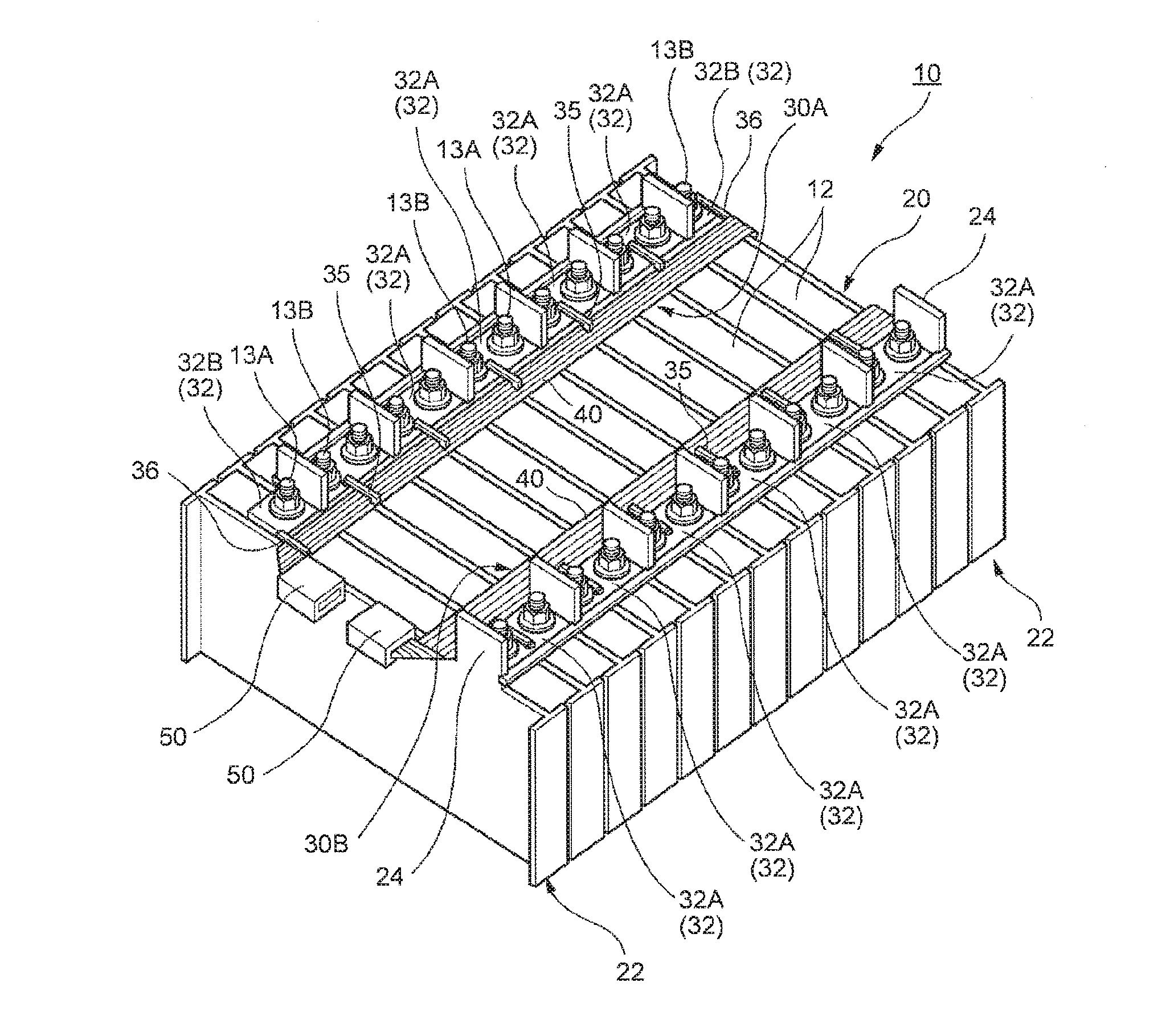
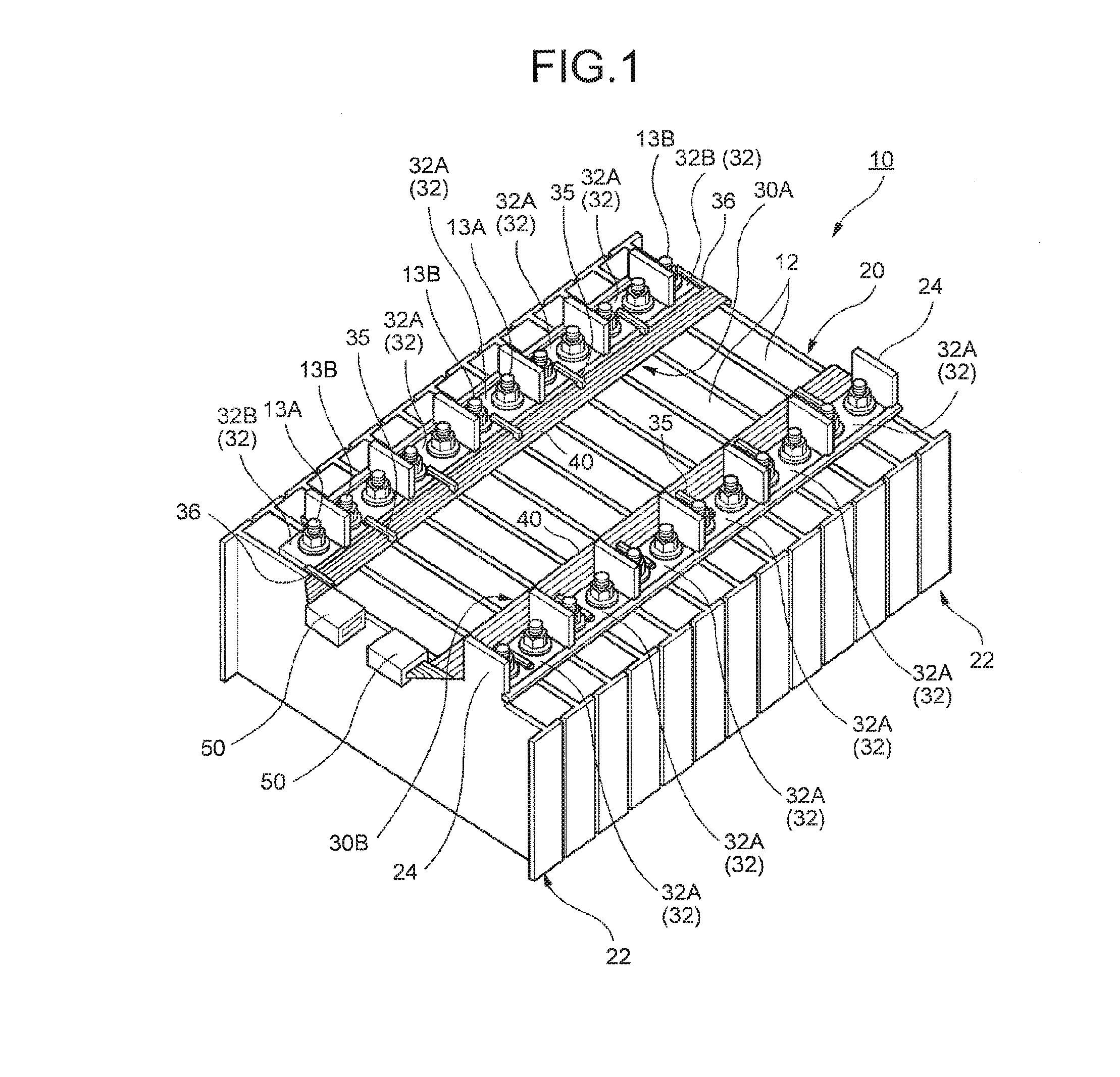
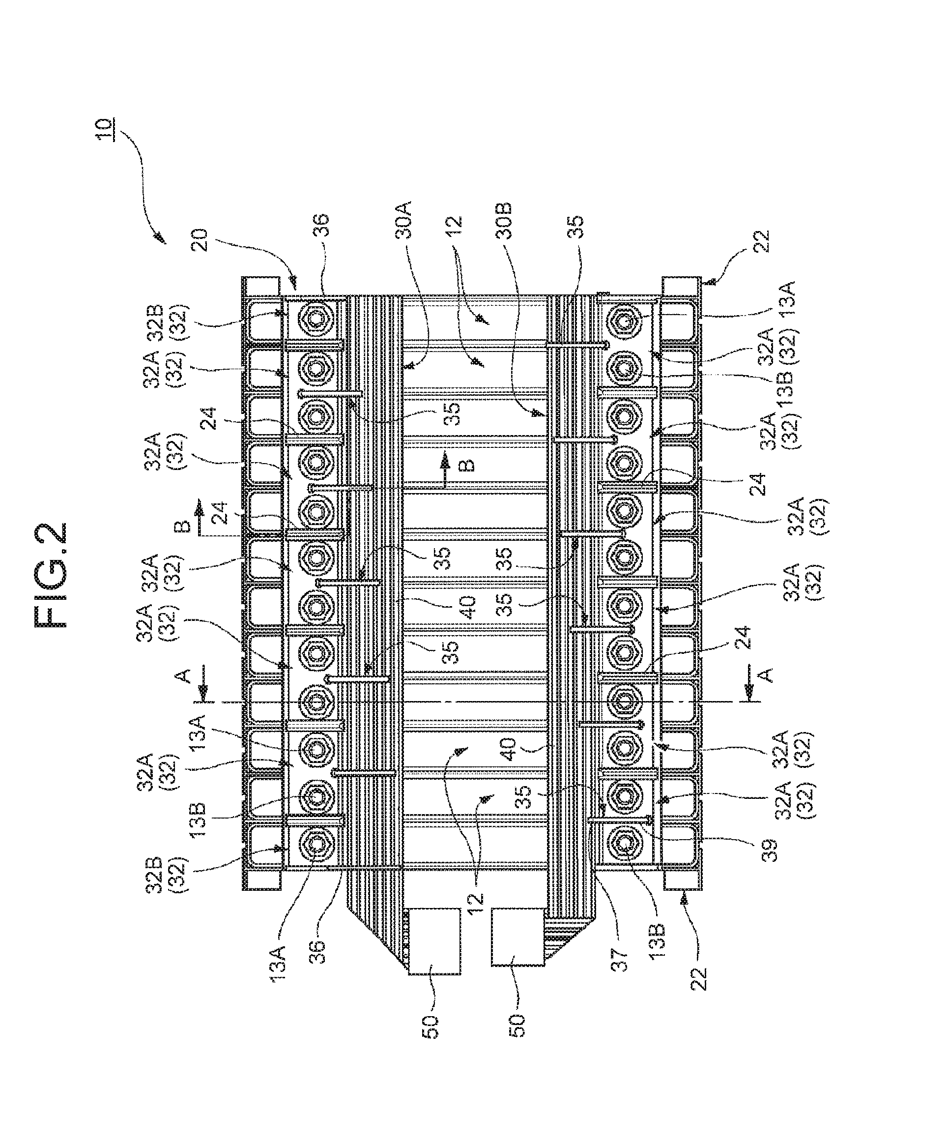
[0041]A battery wiring module is provided in a battery pack and is provided in a battery module including a plurality of battery cells. The battery pack is mounted on, for example, a vehicle such as an electric vehicle or a hybrid vehicle and is used to transmit or receive (charge or discharge) electric power to or from a rotator (an electric motor, a generator, and an electric generator) as a drive source of the vehicle through an inverter. In the battery module, the battery cells overlap one another in the same direction so that one-side electrode terminals of the battery cells are arranged in a line and the other-side electrode terminals thereof are arranged in a line. For example, as the battery module, the electrode terminals are arranged in a row so that a cathode terminal and an anode terminal are alternately arranged or the same electrode terminals are arranged. In the battery pack, one-side electrode terminals of a predetermined plurality of battery cells are connected to e...

second embodiment

[0065]Next, a battery wiring module 80 according to a second embodiment of the present invention will be described. In the embodiment, a form of connecting the busbar 32A and the linear conductor 21 in the battery wiring modules 30A and 30B of the first embodiment is changed. For this reason, in the description of the embodiment below, a description will be made by exemplifying the battery wiring module 30B of the first embodiment. Accordingly, the same reference numerals will be given to the same components as the battery wiring module 30B, and the repetitive description thereof will be omitted. In addition, the battery wiring module 80 according to the embodiment is exemplified based on the configuration of the battery wiring module 30B including one kind of busbar 32A. However, the same applies to the configuration based on the battery wiring module 30A including two kinds of busbars 32A and 32B.

[0066]In the battery wiring module 80 according to the embodiment, the elongated flat...

third embodiment

[0070]Next, a battery wiring module 90 according to a third embodiment of the present invention will be described. In the embodiment, a form of connecting between the busbar 32A and the linear conductor 21 in the battery wiring modules 30A and 30B of the first embodiment is changed. For this reason, in the description of the embodiment below, a description will be made by exemplifying the battery wiring module 30B of the first embodiment. Accordingly, the same reference numerals will be given to the same components as the battery wiring module 30B, and the repetitive description thereof will be omitted. In addition, the method for manufacturing the battery wiring module 90 according to the embodiment is exemplified based on the configuration of the battery wiring module 30B including one kind of busbar 32A. However, the same applies to the configuration based on the battery wiring module 30A including two kinds of busbars 32A and 32B.

[0071]In the battery wiring module 90 according t...


PUM


Abstract

Provided is a battery wiring module including: a plurality of linear conductors disposed in parallel with a predetermined gap therebetween; a plurality of busbars disposed in parallel along at least one of the linear conductors disposed at both ends having a predetermined gap therebetween so as to electrically connect electrode terminals provided in at least two battery cells connected to each other in the same direction among the plurality of battery cells overlapping each other in the same direction, the electrode terminals being arranged in the same direction; a first insulating resin portion which integrally coats the outer peripheral portions of the plurality of linear conductors and a side edge portion adjacent to the linear conductor in the plurality of busbars; and a connection conductor which electrically connects the linear conductor and the busbar to each other.

Description

CROSS-REFERENCE TO RELATED APPLICATION[0001]This application is a continuation application of International Application PCT / JP2014 / 084359, filed on Dec. 25, 2014, and designating the U.S., the entire contents of which are incorporated herein by reference.BACKGROUND OF THE INVENTION[0002]1. Field of the Invention[0003]The present invention relates to a battery wiring module.[0004]2. Description of the Related Art[0005]An in-vehicle battery pack which is connected to a power converter for driving a motor is mounted on a vehicle such as a hybrid vehicle or an electric vehicle. The battery pack is equipped with a battery module including a plurality of battery cells. In the battery module, the battery cells overlap one another so that one-side electrode terminals of the battery cells are arranged in a line and the other-side electrode terminals thereof are arranged in a line. In the battery pack, the electrode terminals of the adjacent battery cells are connected to each other by a conn...

Claims


Application Information

Patent Timeline
IPC IPC(8): H01M2/20H01M2/10H01R25/16H01M50/529H01M50/209H01M50/503H01M50/569
CPCH01M2/206H01M2220/20H01M2/1077H01R25/162H01M10/482Y02E60/10H01M50/209H01M50/569H01M50/503
Inventor ICHIKAWA, YOSHIAKIMUKASA, HIROTAKAKOIKE, HIROKUNI
Owner YAZAKI CORP
Learn More