Brushless motor

a brushless motor and motor body technology, applied in the direction of electrical equipment, dynamo-electric machines, supports/enclosements/casings, etc., can solve the problems of affecting the performance of the shaft bearing, the flow of cooling air, and the penetration pathway of water droplets at the gaps in the outer peripheral portion of the fan motor, so as to improve the water stopping capability of the inner labyrinth structure, the effect of increasing the flow path length and improving the water stopping capability of the outer labyrinth structur

Active Publication Date: 2016-09-15
DENSO CORP
View PDF3 Cites 2 Cited by
  • Summary
  • Abstract
  • Description
  • Claims
  • Application Information

AI Technical Summary

Benefits of technology

[0025]According to the brushless motor of the sixth aspect, the leading end side of the first water stopping wall overlaps with the leading end side of the second water stopping wall along the axial direction of the motor shaft. The water stopping capability of the inner labyrinth structure can thereby be further improved since the flow path inside the inner labyrinth structure bends and the flow path length is increased.
[0026]Similarly, the leading end side of the third water stopping wall overlaps with the leading end side of the fourth water stopping wall of the motor shaft. The water stopping capability of the outer labyrinth structure can thereby be further improved since the flow path inside the outer labyrinth structure bends and the flow path length is increased.

Problems solved by technology

In such brushless motors, the performance of the shaft bearing is liable to decrease when exposed to water due to water droplets having penetrated through to the inside the rotor housing.
However, in the vehicle fan motor described above, penetration pathways for water droplets are liable to arise at gaps in an outer peripheral portion of the fan motor, namely, at gaps formed between the rotor housing, the fixing portion of the fan, and the shroud.
However, in such cases, flow of cooling air that cools a winding coil section wound around teeth of the stator and that is expelled toward the radial direction outside of the fan motor is liable to be hindered by the labyrinth structure.

Method used


Image

  • Brushless motor
  • Brushless motor
  • Brushless motor

Examples


Embodiment Construction

[0033]Explanation follows regarding an exemplary embodiment of the present disclosure based on the drawings.

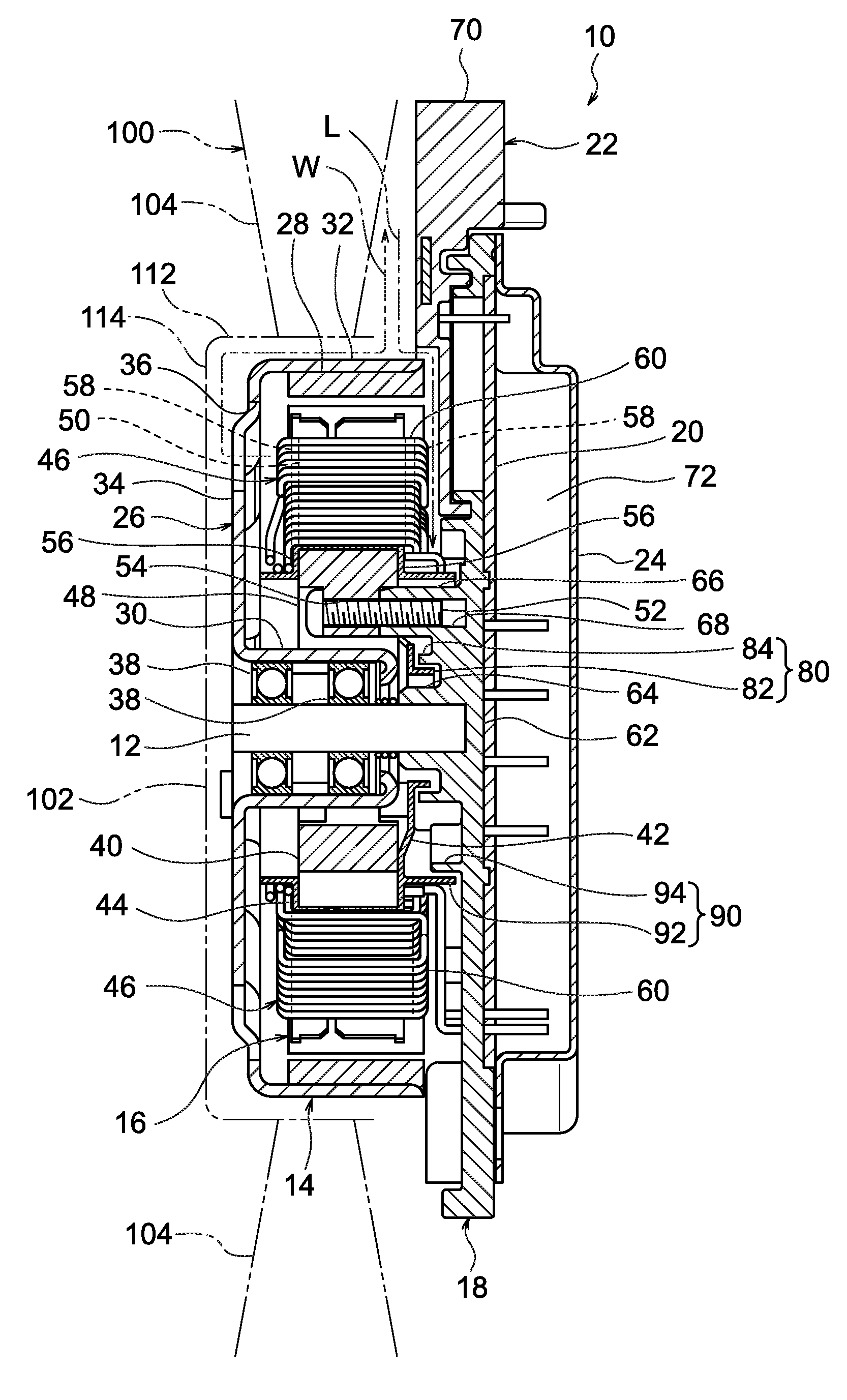
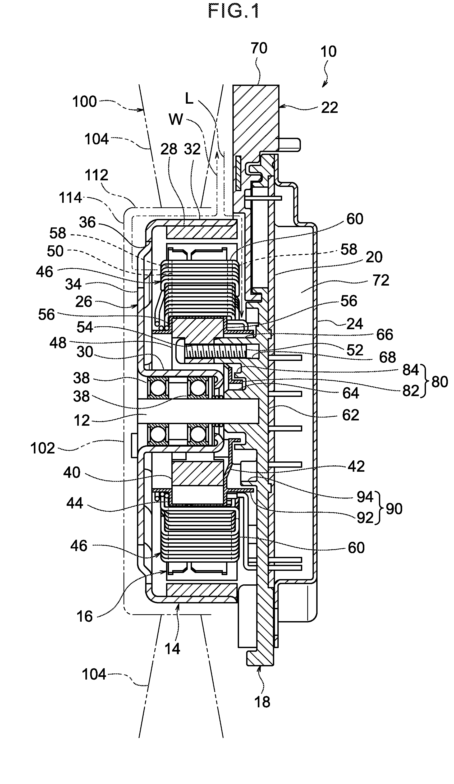
[0034]As illustrated in FIG. 1, a brushless motor 10 according to the exemplary embodiment of the present disclosure includes a motor shaft 12, a rotor 14, a stator 16, a centerpiece 18, a circuit board 20, a connecting member 22, and a board case 24.

[0035]The rotor 14 includes a rotor housing 26 and a rotor magnet 28. The rotor housing 26 includes a circular cylinder shaped shaft bearing housing section 30 provided at the outer radial direction side of the motor shaft 12, and an bottomed-cylinder shaped outer cylinder section 32 formed at the radial direction outside of the shaft bearing housing section 30. The rotor magnet 28 is provided at an inner peripheral face of the outer cylinder section 32.

[0036]An opening is formed at one axial direction side of the outer cylinder section 32, and a bottom wall portion 34 is formed at the other radial direction side of the outer cyli...


PUM


Abstract

There is provided a brushless motor including (1) a motor shaft, (2) an insulator that includes a ring-shaped insulating portion covering the ring-shaped unit, (3) a centerpiece that includes a main body section that supports the motor shaft, (4) a first water stopping wall that is formed in a ring shape along the circumferential direction of the motor shaft, and that extends along the axial direction of the motor shaft from the ring-shaped insulating portion toward the main body section, and (5) a second water stopping wall that is formed in a ring shape along the circumferential direction of the motor shaft, that extends out along the axial direction of the motor shaft from the main body section toward the ring-shaped insulating portion, and that, together with the first water stopping wall, configures a labyrinth structure.

Description

CROSS-REFERENCE TO RELATED APPLICATION[0001]This application claims priority under 35 USC 119 from Japanese Patent Application No. 2015-047252, filed on Mar. 10, 2015, the disclosure of which is incorporated by reference herein.BACKGROUND[0002]1. Technical Field[0003]The present disclosure relates to a brushless motor.[0004]2. Related Art[0005]A conventional outer rotor type brushless motor provided with a motor shaft, a rotor housing rotatably supported on the motor shaft through a shaft bearing, and a stator housed inside the rotor housing is known (for example, see Japanese Patent Application Laid-Open (JP-A) No. 2014-36525).[0006]In such brushless motors, the performance of the shaft bearing is liable to decrease when exposed to water due to water droplets having penetrated through to the inside the rotor housing. A brushless motor provided with a labyrinth structure has therefore been proposed for suppressing the shaft bearing from being exposed to water (for example, see JP-A ...

Claims


Application Information

Patent Timeline
Patent Type & Authority Applications(United States)
IPC IPC(8): H02K5/10H02K5/16
CPCH02K5/161H02K5/10
Inventor MURASE, AKIO
Owner DENSO CORP
Why Eureka
Try Eureka