
External power supply and system connection detection unit applied thereto

a detection unit and power supply technology, applied in the field of external power supply and system connection detection units, can solve the problems of reducing the power consumption of the external power supply, affecting the instant disclosure of the output voltage, and affecting the efficiency of the power electronics conversion, etc., to achieve the effect of facilitating the disclosure of the instant disclosur

Inactive Publication Date: 2016-09-15
LITE ON ELECTRONICS (GUANGZHOU) LTD +1
View PDF0 Cites 1 Cited by
  • Summary
  • Abstract
  • Description
  • Claims
  • Application Information

AI Technical Summary

Benefits of technology

The invention is a power supply that uses a special matching system to detect the voltage of the device it is connected to. This information is then used to control the power source in two different modes - a deep sleeping mode and a normal operating mode. The technical effect of this is that the power supply can automatically adjust its power source to the needs of the device, ensuring the best performance and efficiency.

Problems solved by technology

Therefore, decreasing the power consumption of the external power supply has become a problem to be overcome at present for persons skilled in the art.
Under the circumstance of continuing improved energy consumption requirements, the burst-mode control is not sufficient to meet the requirements of approaching extreme low power consumption of the converter.
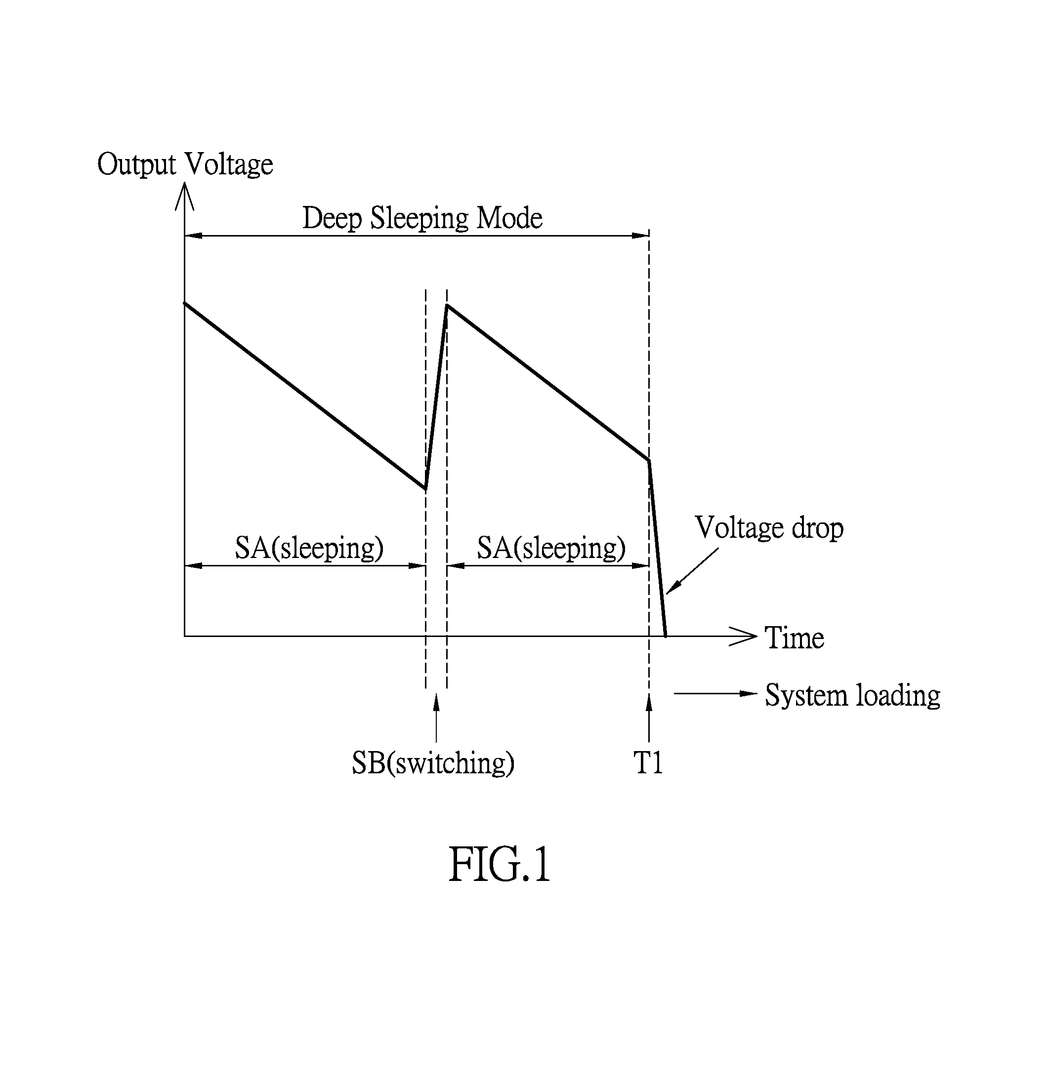
However, due to the time interval of intermittent work being too long, the output voltage increases greatly and decreases greatly.
As such, the output voltage cannot be stable at the required DC voltage for the general system work.
Because of the unstable output voltage, if the computer without a battery uses this operation mode, the power supply would not recover the normal operation mode fast enough when the load draw happens, resulting in too low output voltage.
It may cause the abnormal operation.

Method used


Image

  • External power supply and system connection detection unit applied thereto
  • External power supply and system connection detection unit applied thereto
  • External power supply and system connection detection unit applied thereto

Examples


Embodiment Construction

[0018]The aforementioned illustrations and following detailed descriptions are exemplary for the purpose of further explaining the scope of the instant disclosure. Other objectives and advantages related to the instant disclosure will be illustrated in the subsequent descriptions and appended drawings.

[0019][An Embodiment of an External Power Supply and a System Connection Detection Unit Applied Thereto]

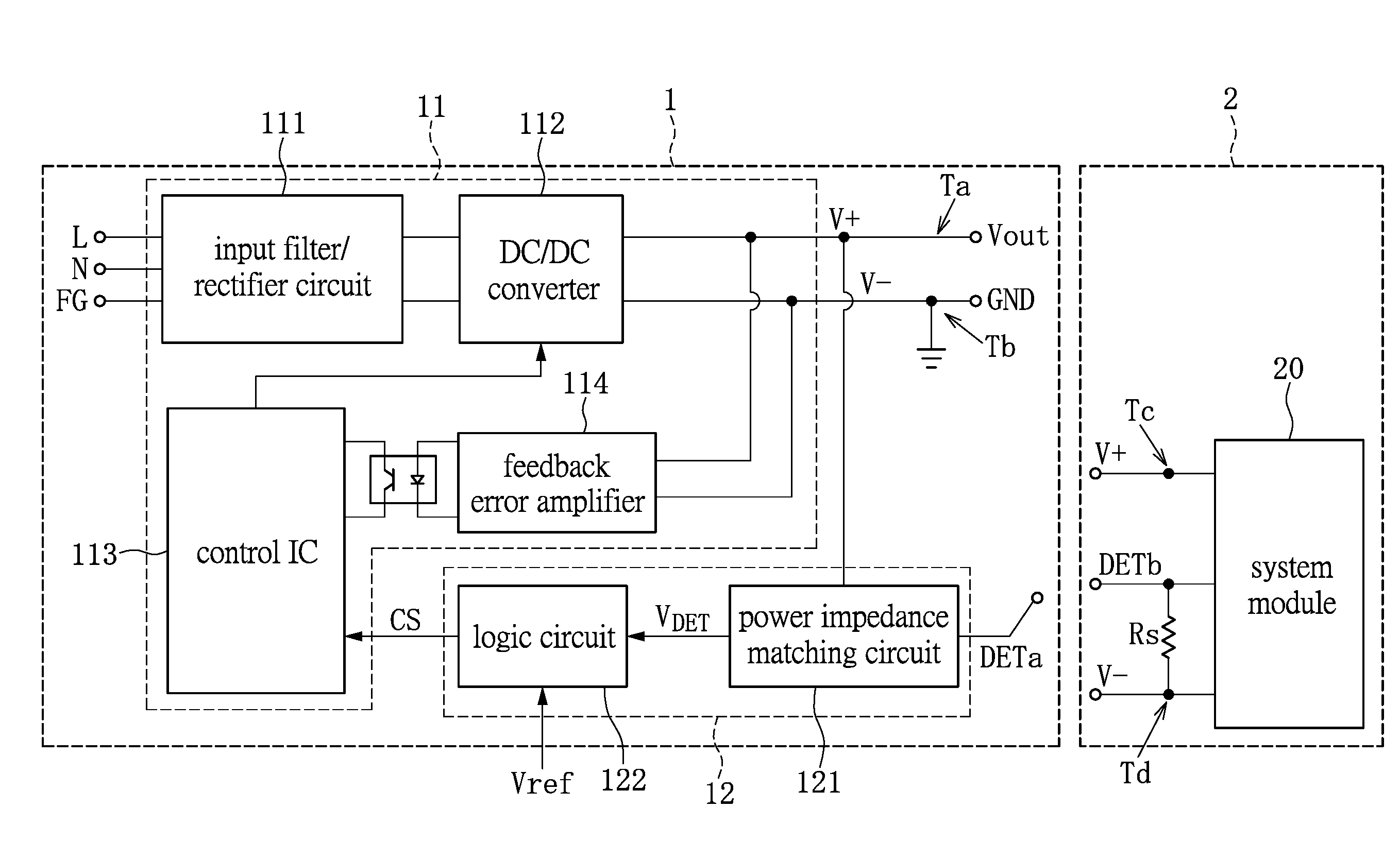
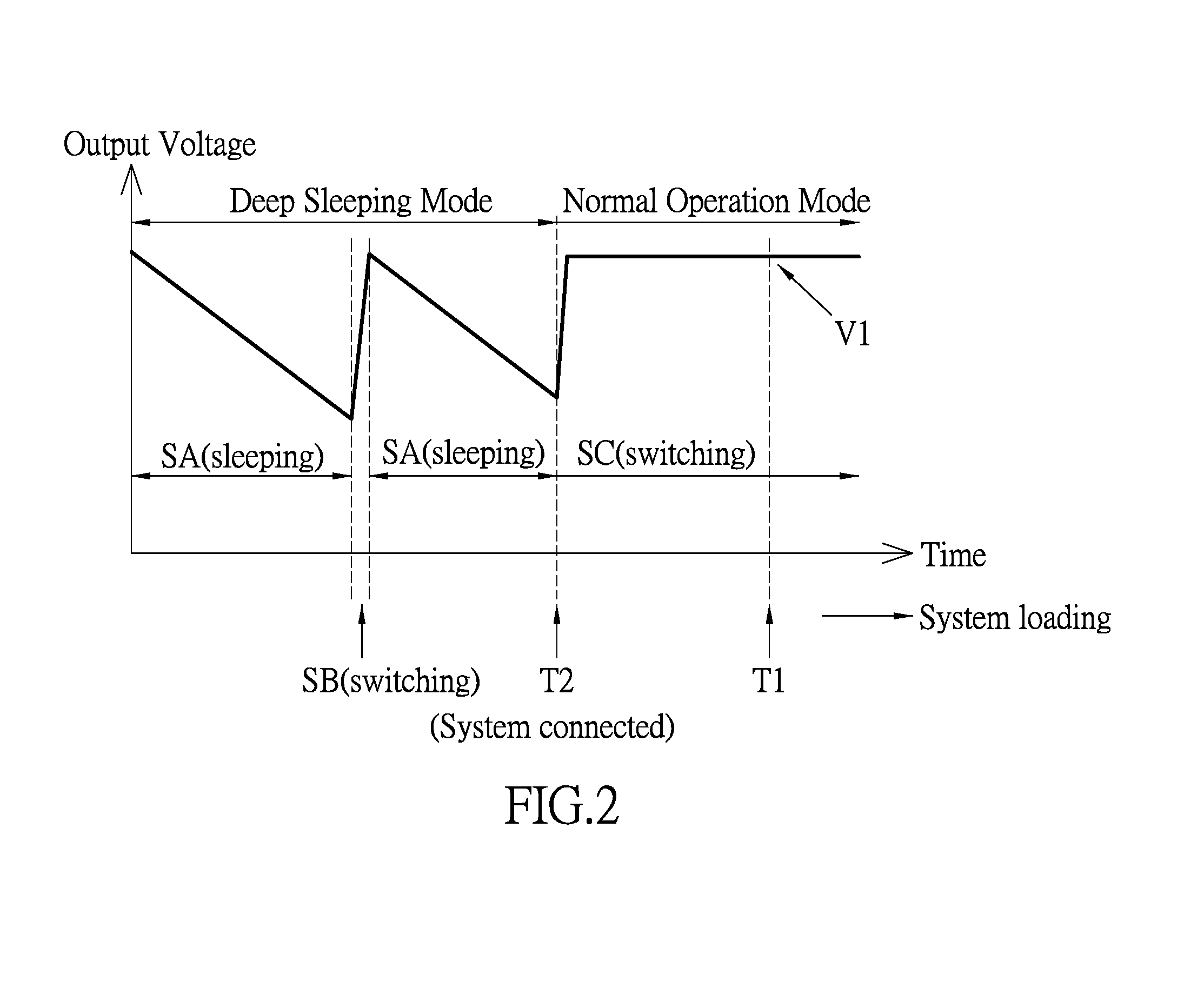
[0020]The external power supply of this embodiment has a normal operation mode and a deep sleeping mode. The power consumption of the external power supply in the deep sleeping mode is less than that of the external power supply in the normal operation mode. Please refer to FIG. 2 showing a waveform diagram of an output voltage of an external power supply according to an embodiment of the instant disclosure. At first, the objective of the external power supply in this embodiment is described. Then, the circuits of the external power supply and the system connection detection unit are...


PUM


Abstract

An external power supply and a system connection detection unit applied thereto are provided. For providing DC power, the external power supply separably connects with a positive input terminal and a negative input terminal of a system through a positive output terminal and a negative output terminal respectively. When the positive output terminal and the negative output terminal are respectively connected to the positive input terminal and the negative input terminal, a system detection terminal connects with a system connection terminal of the system, and a connection status signal generated by the system connection detection unit switches the operation of the external power supply from a deep sleeping mode to a normal operation mode. The system connection terminal is electrically connected to one of the positive input terminal and the negative input terminal through at least a first resistive element.

Description

BACKGROUND OF THE INVENTION[0001]1. Field of the Invention[0002]The instant disclosure relates to a power supply; in particular, to an external power supply and a system connection detection unit applied thereto.[0003]2. Description of Related Art[0004]Enhanced environmental awareness in recent years and global warming have forced saving energy to become one of the major policies of most countries in the world. For the purpose of power saving, the US Department of Energy has developed low-power specifications for all the information and electronic devices. For example, energy efficiency level V1 (Efficiency>88%, Power input<0.21 W at no load) is required for a external power supply. The European Union also has adopted the advanced power saving code CoC tier I (Efficiency>89%, Power input<0.25 W at no load) & tier II (Efficiency>89%, Power input<0.15 W at no load). Therefore, decreasing the power consumption of the external power supply has become a problem to be ov...

Claims


Application Information

Patent Timeline
IPC IPC(8): H02M1/08H03H7/40
CPCH02M1/08H02M2001/0032H03H7/40G01R15/04H02J7/0036Y02B70/10H02M1/0035H02M1/0032
Inventor CHAO, SHAN-JENGUAN, YEH
Owner LITE ON ELECTRONICS (GUANGZHOU) LTD
Learn More