Driving device

a technology of driving device and movable body, which is applied in the direction of device details, devices, and piezoelectric/electrostrictive device details, etc., can solve the problems of unstable movement speed, difficult to make the movement speed of the movable body high, and the inability to pitch feed the moving body with certainty

Active Publication Date: 2016-09-15
MURATA MFG CO LTD
View PDF3 Cites 14 Cited by
  • Summary
  • Abstract
  • Description
  • Claims
  • Application Information

AI Technical Summary

Benefits of technology

[0033]With the driving device according to the present disclosure, by using flexural vibration and another type of vibration or vibration of a coupled mode excited in the plate-shaped driving unit, the movable body can be made to move stably and with certainty without the occurrence of backward movement and the movement speed of the movable body can be stabilized.

Problems solved by technology

Consequently, the movable body cannot be pitch fed with certainty.
Therefore, it is difficult to make the movement speed of the movable body high and the movement speed is unstable.
In this case, it is not easy to generate flexural vibration and radial-direction expansion-contraction vibration with the same period.
Consequently, it is difficult to pitch feed the movable body and it is also difficult to stabilize the movement speed of the movable body.

Method used


Image

  • Driving device
  • Driving device
  • Driving device

Examples


first embodiment

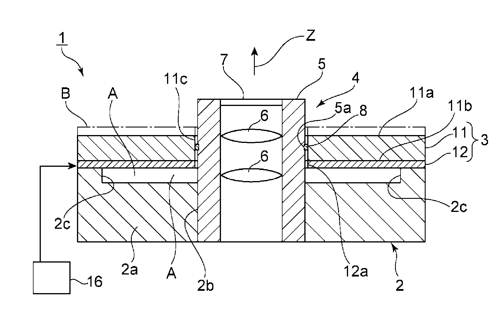
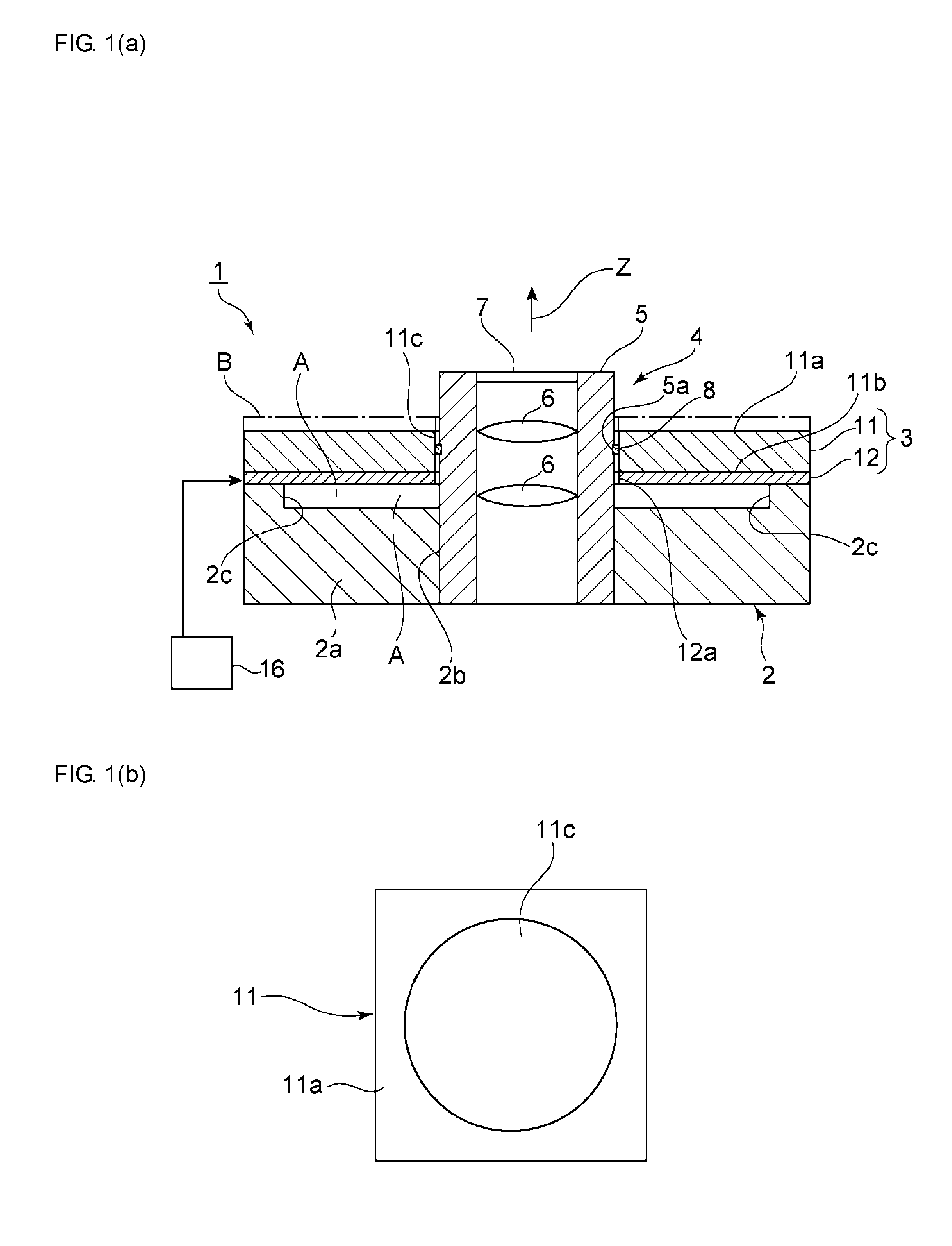
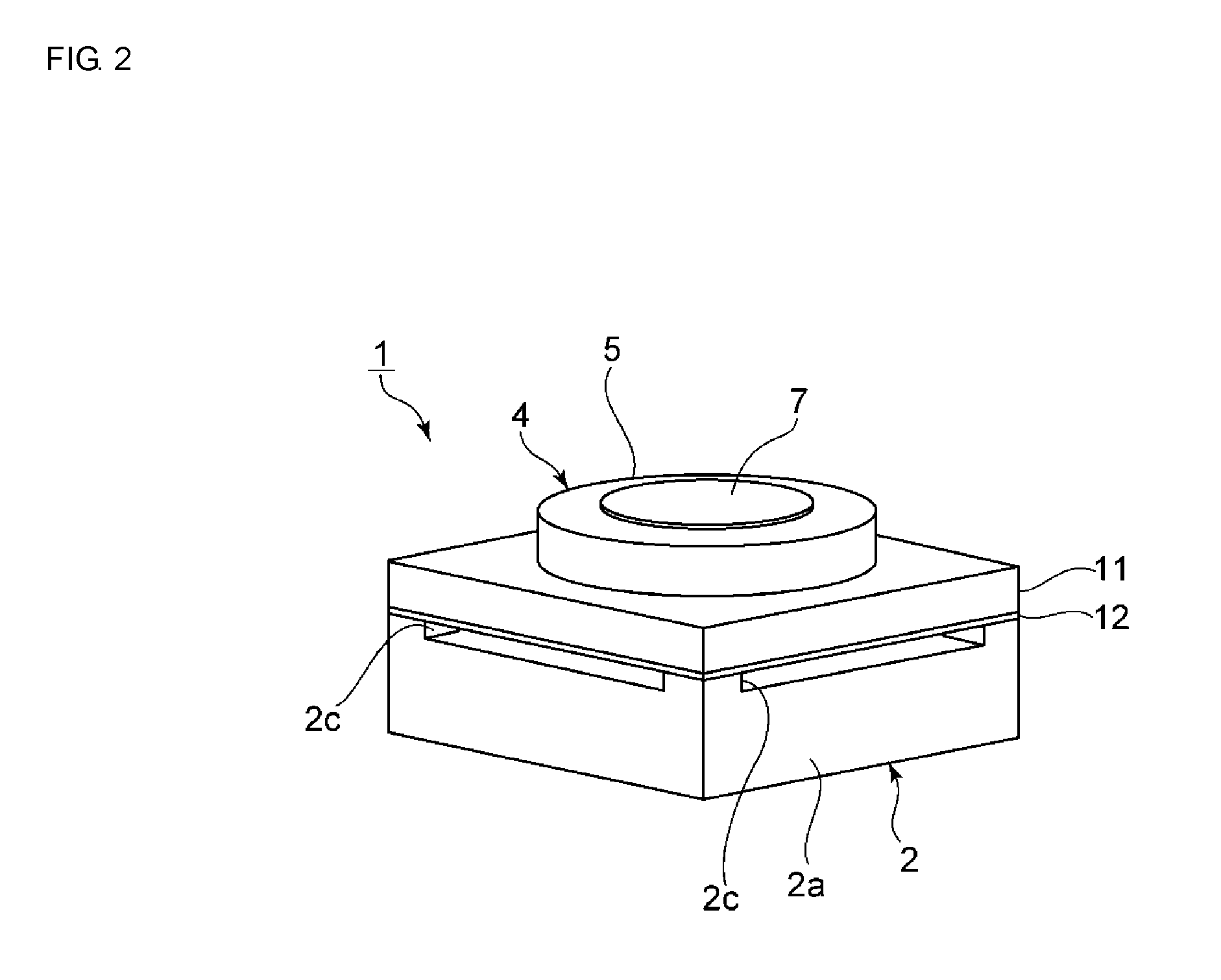
[0075]FIG. 2 is a perspective view illustrating the exterior of a driving device according to the present invention and FIG. 1(a) is a front sectional view of the same.

[0076]A driving device 1 of this embodiment includes a support 2. A driving unit 3 is fixed to the top of the support 2. In this embodiment, a movable body 4 is moved by the driving unit 3.

[0077]As illustrated in the perspective view in FIG. 2, the movable body 4 includes a cylindrical holder 5. A plurality of lenses 6 are arranged inside the holder 5. In addition, a transparent plate 7 is attached so as to seal the end surface of a cavity of the holder 5.

[0078]The driving device 1 of this embodiment causes the movable body 4, which includes the lenses 6, to move in an axial direction of the cylindrical holder 5. This driving device 1 can be suitably used as a lens driving device that includes camera lenses, for example. Arrow Z in FIG. 1(a) indicates the axial direction, and the movable body can be pitch fed in the a...

third embodiment

[0120]Referring to FIGS. 16 to 18, a driving device in which the other type of vibration is undulating vibration will be described as a

[0121]In the third embodiment, a rectangular-frame-shaped driving unit 33 is used, similarly to as in the second embodiment. The driving unit 33 has the same configuration as that of the second embodiment. In this embodiment, the driving unit 33 vibrates in a bending mode as illustrated by the vibration shape in FIG. 16. At the same time, the driving unit 33 also vibrates in undulating vibration as illustrated by the vibration shape in FIG. 17. In this embodiment, the interval between the resonant frequencies of the two types of vibration is adjusted such that the flexural vibration and the area expansion vibration are generated with the same period when driving is performed with a certain driving pulse signal. Therefore, the driving unit 33 is designed in this embodiment as well.

[0122]FIG. 18 illustrates the impedance characteristics of the driving ...

fifth embodiment

[0128]FIG. 21 is a plan view of a driving device according to the present invention and FIG. 22 is a perspective view seen from a bottom surface side.

[0129]A driving device 51 includes a driving unit 53. In this embodiment, the driving unit 53 has a rectangular-frame-like planar shape. It should be pointed out that just the outline of the driving unit 53 including the elastic body 11 is illustrated in a schematic manner in FIGS. 21 and 22. That is, only the elastic body 11, a movable body 54 and pressing contact members 58 are illustrated. The piezoelectric element and so forth have the same configurations as those in the first to fourth embodiments described above.

[0130]In this embodiment, the elastic body 11 has a rectangular outer shape in plan view and the cavity 11c also has a rectangular shape in plan view. The movable body 54 is arranged inside the cavity 11c of the elastic body 11. The movable body 54 has a rectangular parallelepiped shape, more specifically, a rectangular p...


PUM


Abstract

A driving device that causes a movable body to move stably with minimal backward movement. The driving device includes a plate-shaped driving unit with an elastic body and a piezoelectric element joined to a main surface of the elastic body. Moreover, the movable body is disposed into a cavity of the elastic body and is moved by being pitch fed when the driving unit is driven. The driving unit vibrates with flexural vibration and one more other vibration modes or with vibration of a coupled mode in which the flexural vibration and the other vibration mode are coupled with each other.

Description

CROSS REFERENCE TO RELATED APPLICATIONS[0001]The present application is a continuation of PCT / JP2014 / 069016 filed Jul. 17, 2014, which claims priority to Japanese Patent Application No. 2013-244599, filed Nov. 27, 2013, and Japanese Patent Application No. 2014-007586, filed Jan. 20, 2014, the entire contents of each of which are incorporated herein by reference.FIELD OF THE INVENTION[0002]The present disclosure relates to a driving device that causes a movable body to move by driving a piezoelectric element, and more specifically relates to a driving device that utilizes a plurality of vibration modes.BACKGROUND[0003]To date, a variety of driving devices that use piezoelectric elements have been proposed as driving devices for causing a lens or the like to move. In below-listed Patent Document 1, a driving member is used that is displaced in an axial direction on the basis of an expansion / contraction operation of a piezoelectric body. A member that is to be driven can be moved by be...

Claims


Application Information

Patent Timeline
Patent Type & Authority Applications(United States)
IPC IPC(8): H02N2/00H01L41/09H01L41/04H01L41/053
CPCH02N2/001H01L41/042H01L41/09H01L41/053H02N2/026G02B7/08H02N2/0015H02N2/003H10N30/20H10N30/88H10N30/802
Inventor GOTO, SEISHIROOTSUKA, MEGUMINOMURA, JUNICHIHAYASHI, KOICHI
Owner MURATA MFG CO LTD
Why Eureka
Try Eureka