
Multi-film continuous coating device and method

A coating equipment and multi-layer technology, applied in the direction of coating, sputtering plating, ion implantation plating, etc., can solve the problems of small sputtering area, high equipment cost, low coating efficiency, etc., and achieve simplified equipment structure, The effect of reducing production costs and reducing equipment footprint

Inactive Publication Date: 2018-09-11
ZHAOQING KERUN VACUUM EQUIP
View PDF0 Cites 1 Cited by
  • Summary
  • Abstract
  • Description
  • Claims
  • Application Information

AI Technical Summary

Problems solved by technology

In actual production, the equipment structure of this method is huge and complex, and the equipment cost is high. At the same time, because the vacuum degree in different coating chambers is difficult to achieve a high degree of consistency, even if the workpiece or substrate passes through multiple coatings continuously, the uniformity of the surface film layer degree is also difficult to guarantee
In addition, the workpiece is generally conveyed by the structure of friction rollers. This method is prone to slipping when the equipment is running at high speed, which affects the normal conveying of the workpiece and the coating quality of the workpiece surface.
[0003] In addition, in the existing vacuum coating equipment, the target door generally adopts a side-opening structure, but for large-scale equipment, this opening method is very inconvenient to operate, and the replacement or maintenance cost of the target is quite high
In order to facilitate installation, a target tube with a small diameter (generally less than 150mm) is generally used, the sputtering area is small, and the coating efficiency is also low, so it is difficult to achieve fast coating operations.

Method used


Image

  • Multi-film continuous coating device and method
  • Multi-film continuous coating device and method
  • Multi-film continuous coating device and method

Examples


Embodiment

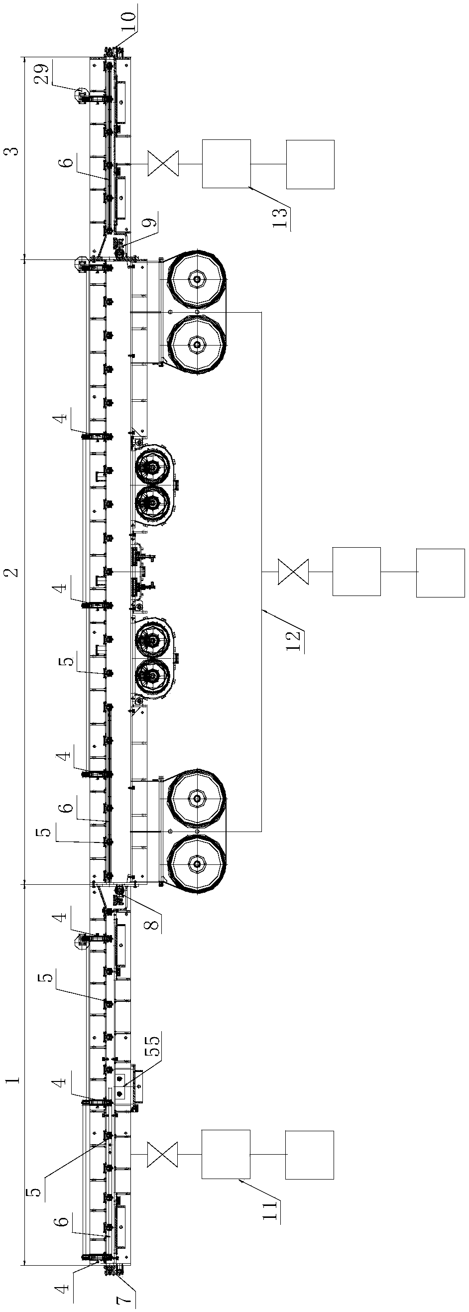
[0053] A kind of multi-layer continuous coating equipment of the present embodiment, such as figure 1 As shown, it includes a surface treatment chamber 1, a multi-film coating chamber 2 and a vacuum chamber 3 connected in sequence, and the surface treatment chamber, the multi-film coating chamber and the vacuum chamber are all provided with a workpiece reciprocating movement mechanism; the workpiece reciprocating movement The mechanism is located below the substrate holder, and a magnetic guide mechanism is provided above the substrate holder. The workpiece reciprocating movement mechanism includes the active driving supporting wheel 4 and the driven supporting wheel 5. The active driving supporting wheel and the driven supporting wheel are respectively arranged in a vacuum On the installation bracket in the vacuum chamber (the vacuum chamber is a surface treatment chamber, a multi-film coating chamber or a film discharge vacuum chamber), a plurality of driven supporting wheels...


PUM


Abstract

The invention discloses a multi-film continuous coating device and method. The device comprises a surface treatment chamber, a multi-film coating chamber and a substrate outlet vacuum chamber which are connected in sequence; each chamber is provided with a workpiece reciprocating moving mechanism; and the workpiece reciprocating moving mechanisms are arranged below a substrate frame, a magnetic steering mechanism is arranged above the substrate frame, active drive supporting wheels and driven bearing wheels in the workpiece reciprocating moving mechanisms are arranged on a mounting support inthe vacuum chamber, the multiple driven bearing wheels are distributed between two adjacent active drive supporting wheels, and under driving of the active drive supporting wheels, the substrate framedoes reciprocated moving along the driven bearing wheels and the magnetic steering mechanism. The method comprises the steps that the workpiece reciprocating moving mechanisms drive the substrate frame and a workpiece to do reciprocated moving in the surface treatment chamber, and repeated surface roughening and cleaning treatment are achieved; reciprocated moving in the multi-film coating chamber is carried out, and multi-film coating is achieved; and finally, the workpiece is conveyed out from the substrate outlet vacuum chamber. The equipment structure can be effectively simplified, and the coating efficiency and the coating uniformity are improved.

Description

technical field [0001] The invention relates to the technical field of vacuum coating, in particular to a multi-layer continuous coating equipment and method. Background technique [0002] In the existing vacuum coating equipment, whether it is a linear coating equipment or a winding coating equipment, the coating method of the workpiece or the substrate is coated in one continuous pass. In this case, the coating equipment generally It is necessary to set up multiple vacuum coating chambers or multiple coating units connected continuously, as well as multiple targets for multiple coatings, so that the thickness of the film layer can reach the desired thickness. In actual production, the equipment structure of this method is huge and complex, and the equipment cost is high. At the same time, because the vacuum degree in different coating chambers is difficult to achieve a high degree of consistency, even if the workpiece or substrate passes through multiple coatings continuou...

Claims


Application Information

Patent Timeline
IPC IPC(8): C23C14/35C23C14/56C23C14/50
CPCC23C14/352C23C14/50C23C14/56
Inventor 朱建明
Owner ZHAOQING KERUN VACUUM EQUIP
Learn More