Splitting machine cutter automatic adjusting device

A technology of automatic adjustment device and slitting machine, which is applied in metal processing and other directions, can solve the problems of reducing adjustment efficiency, complicated adjustment of cutter spacing, etc., and achieves the effect of simple adjustment.

Active Publication Date: 2018-10-16
重庆佑威电子有限公司
View PDF5 Cites 3 Cited by
  • Summary
  • Abstract
  • Description
  • Claims
  • Application Information

AI Technical Summary

Problems solved by technology

Therefore, when adjusting the distance between the cutters, it is necessary to disassemble the cutting shaft and the positioning shaft in order to replace the standard block, and then fix the positioning blocks at both ends on the positioning shaft, which makes the adjustment of the distance between the cutters more complicated
In addition, the standard block usually consists of several series. When a certain distance between the cutting knives is required, a combination of multiple series of standard blocks is usually required, which further reduces the adjustment efficiency.

Method used


Image

  • Splitting machine cutter automatic adjusting device
  • Splitting machine cutter automatic adjusting device
  • Splitting machine cutter automatic adjusting device

Examples


Embodiment Construction

[0020] The present invention will be described in further detail below by means of specific embodiments:

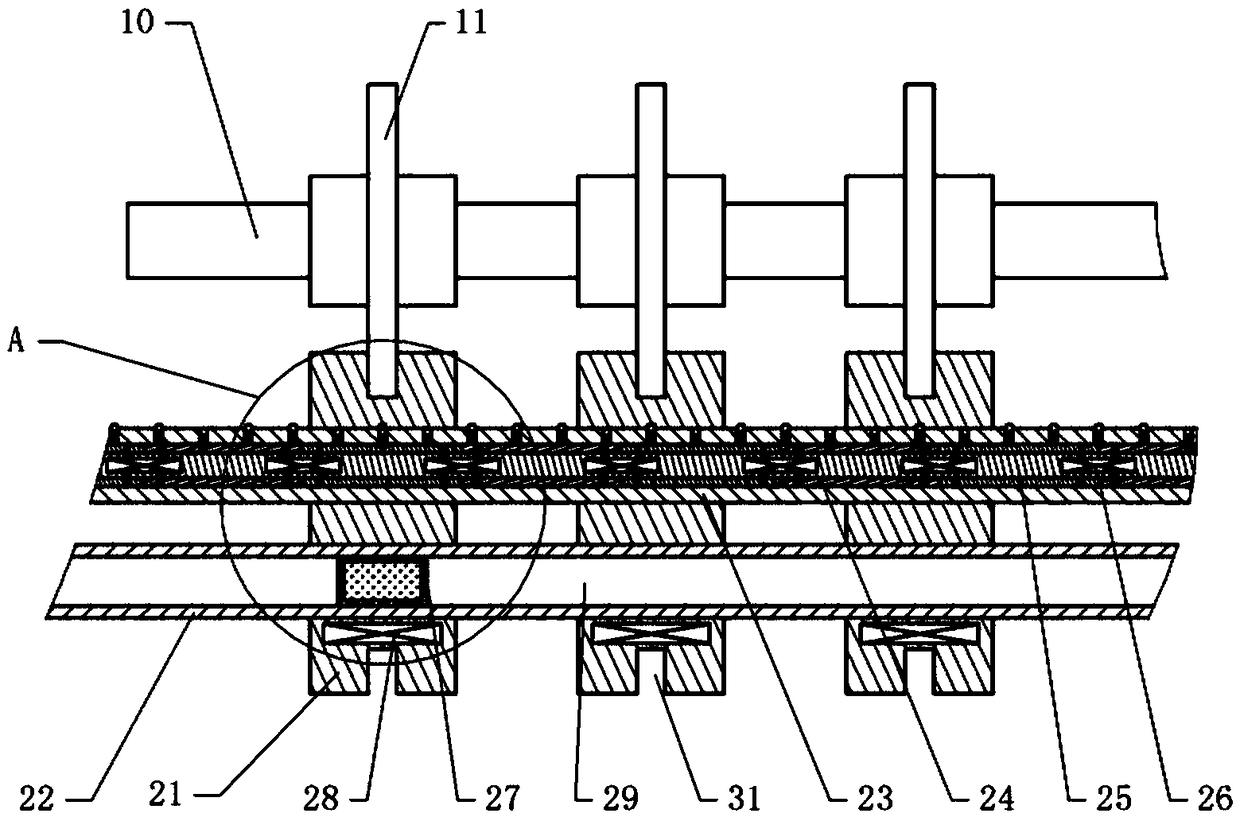
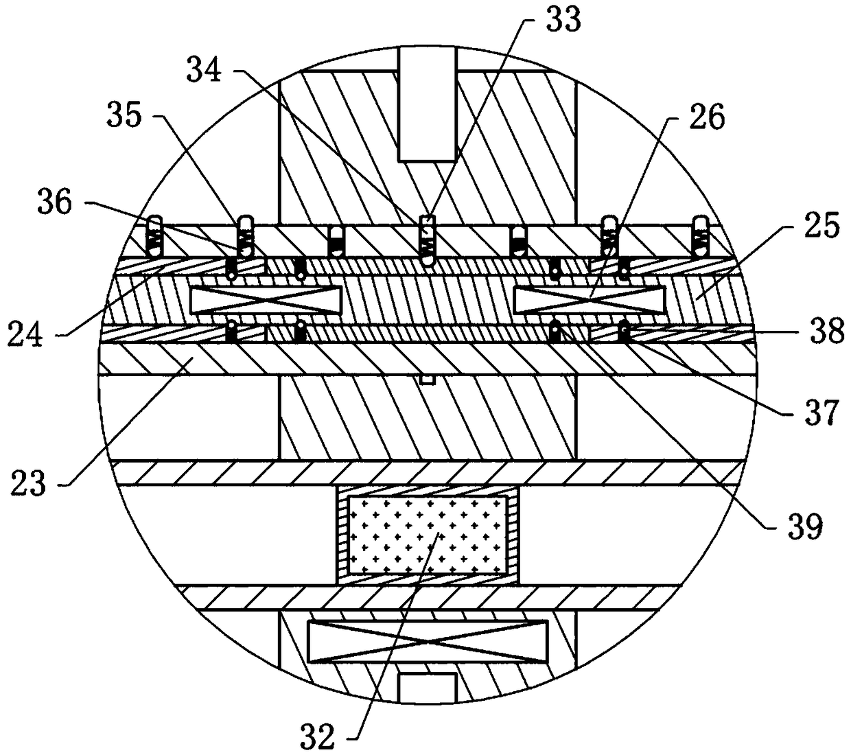
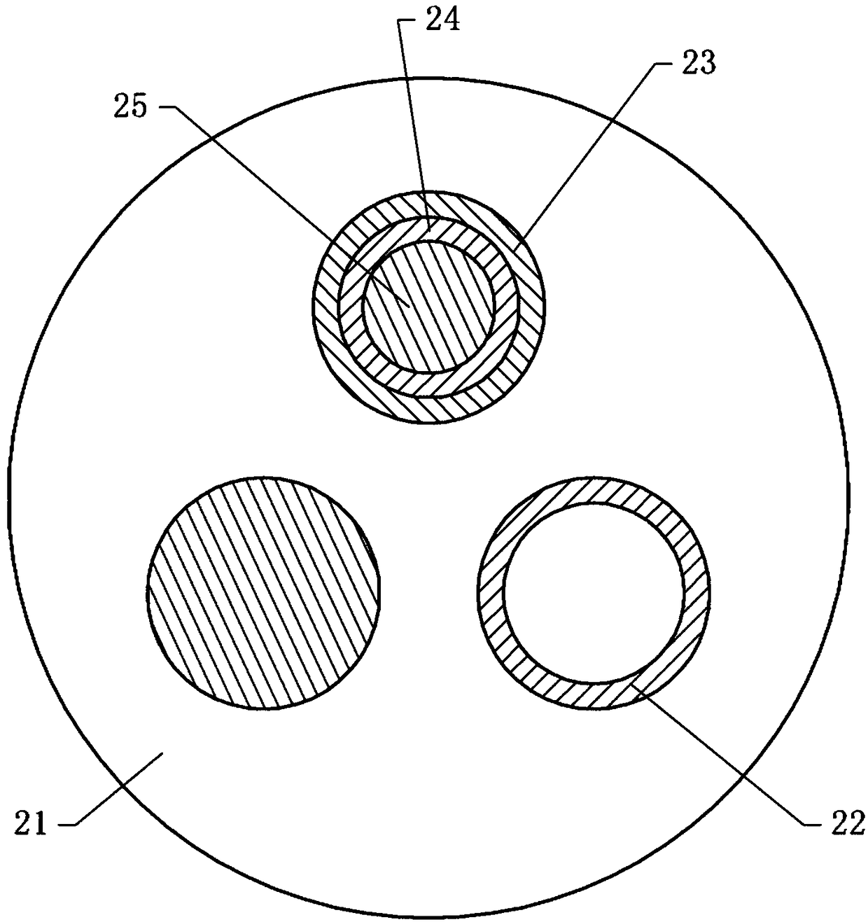
[0021] The reference signs in the drawings of the description include: cutting shaft 10, cutter 11, positioning block 21, hydraulic rod 22, outer jacket 23, ring body 24, inner rod 25, second electromagnet 26, piston 27, first electromagnetic Iron 28, hydraulic chamber 29, annular groove 31, permanent magnet 32, positioning groove 33, positioning column 34, stage clip 35, ball 36, extension spring 37, steel ball 38, driving groove 39.

[0022] The embodiment is basically as figure 1 , figure 2 with image 3 Shown:

[0023] The cutter automatic adjustment device of the slitting machine of the present embodiment comprises a slitting shaft 10 and a positioning shaft, ten cutting knives 11 are slidably connected on the slitting shaft 10, and a positioning block 21 cooperating with the cutting knives 11 is provided on the positioning shaft, and the positioning The block 2...


PUM


Abstract

The invention relates to cutter adjusting devices and particularly discloses a splitting machine cutter automatic adjusting device comprising a splitting shaft and a locating shaft. The splitting shaft and the locating shaft are each slidably connected with a plurality of cutters and locating blocks. The locating blocks are provided with annular grooves. The cutters are embedded into the annular grooves. The locating shaft comprises a guide rod, a hydraulic rod and a locating rod. A hydraulic cavity is formed in the hydraulic rod. A piston made of a permanent magnet is arranged in the hydraulic cavity. First electromagnets are arranged in the locating blocks. The locating rod comprises an outer sleeve, an inner rod and ring bodies arranged between the outer sleeve and the inner rod. The outer sleeve is provided with a locating hole. A locating column, balls and a compressed spring are arranged in the locating hole. Locating grooves are formed in the locating blocks. The ring bodies areprovided with spirally arranged hemispherical grooves. The balls can be embedded into the hemispherical grooves. A second electromagnet fixed to the inner rod is arranged between every two adjacent ring bodies. The ring bodies are provided with blind holes. Steel balls and tension springs are arranged in the blind holes. The steel balls and the bottoms of the blind holes are connected through thetension springs. The inner rod is provided with a driving groove. Adjusting of the cutter spaces can be simpler and more convenient through the splitting machine cutter automatic adjusting device.

Description

technical field [0001] The invention relates to a cutter adjusting device, in particular to an automatic adjusting device for cutters of a slitting machine. Background technique [0002] Slitting machine is a kind of mechanical equipment that cuts wide paper, mica tape or film into multiple narrow-width materials. It is often used in papermaking machinery, wire and cable mica tape, and printing and packaging machinery. When our company processes foam, electronic insulation sheets, copper foil, aluminum foil and other materials, it needs to use a slitting machine for slitting. Due to different product series, the raw materials need to be cut into different widths, so when processing different products, the distance between the cutters needs to be adjusted. The cutting part of the existing slitting machine comprises a slitting shaft and a positioning shaft, on which a plurality of cutting knives are slidably connected, the positioning shaft is provided with a positioning bloc...

Claims


Application Information

Patent Timeline
Patent Type & Authority Applications(China)
IPC IPC(8): B26D7/26
Inventor 饶丽丽
Owner 重庆佑威电子有限公司
Why Eureka
Try Eureka