Separation device for three-phase fluid, method for making thereof, and method for separating a three-phase fluid

a three-phase fluid and separation device technology, applied in separation processes, liquid degasification, chemistry apparatus and processes, etc., can solve the problems of inability to meet the needs of two-phase separators and fall into disuse, and achieve the effects of reducing control times, low cost and convenient operation

Active Publication Date: 2016-09-22
YPF SA
View PDF2 Cites 9 Cited by
  • Summary
  • Abstract
  • Description
  • Claims
  • Application Information

AI Technical Summary

Benefits of technology

[0010]The present invention solves the need for a low cost three-phase separation and measuring device which reduces control times, is easy to operate and which performs reliable measurements, a need specially present in mature oil reservoirs,
[0011]Furthermore, the present invention solves such needs by means of vertical two-phase separators, which are among the elements more often used in the oil industry, without having to invest large amounts of money in horizontal three-phase separators.
[0012]As it is well known in the art, when oil reservoirs approach completion, two phase separators are no longer suitable and fall into disuse. The present invention allows prolonging their lifespan, utilizing them in reservoirs near depletion, transforming said two-phase vertical separators into three-phase vertical separators, so as to streamline well control operations, and eliminate control tanks and errors associated with measurements.
[0052]The device and methods of the present invention provides vertical separator with a very low investment relating to equipment and assembly costs, since it allows the re-use or recycle at the original location of equipment that would otherwise be decommissioned.
[0053]Likewise, de device of the present invention features a dynamic operation since its use, restart, calibration, repair, and disassembling are easy. Its operation is stable, without the need for further adjustments once calibrated, its maintenance cost is low and it is versatile, adaptable for a wide range of liquid flows, depending on the capacity of the vessel. It is suitable for use on reservoirs with low GOR (gas oil ratio) and high water cuts of the type encountered on mature reservoirs.

Problems solved by technology

As it is well known in the art, when oil reservoirs approach completion, two phase separators are no longer suitable and fall into disuse.

Method used


Image

  • Separation device for three-phase fluid, method for making thereof, and method for separating a three-phase fluid
  • Separation device for three-phase fluid, method for making thereof, and method for separating a three-phase fluid
  • Separation device for three-phase fluid, method for making thereof, and method for separating a three-phase fluid

Examples


Embodiment Construction

[0056]The device and methods of the present invention are further described in detail with reference to the accompanying figures.

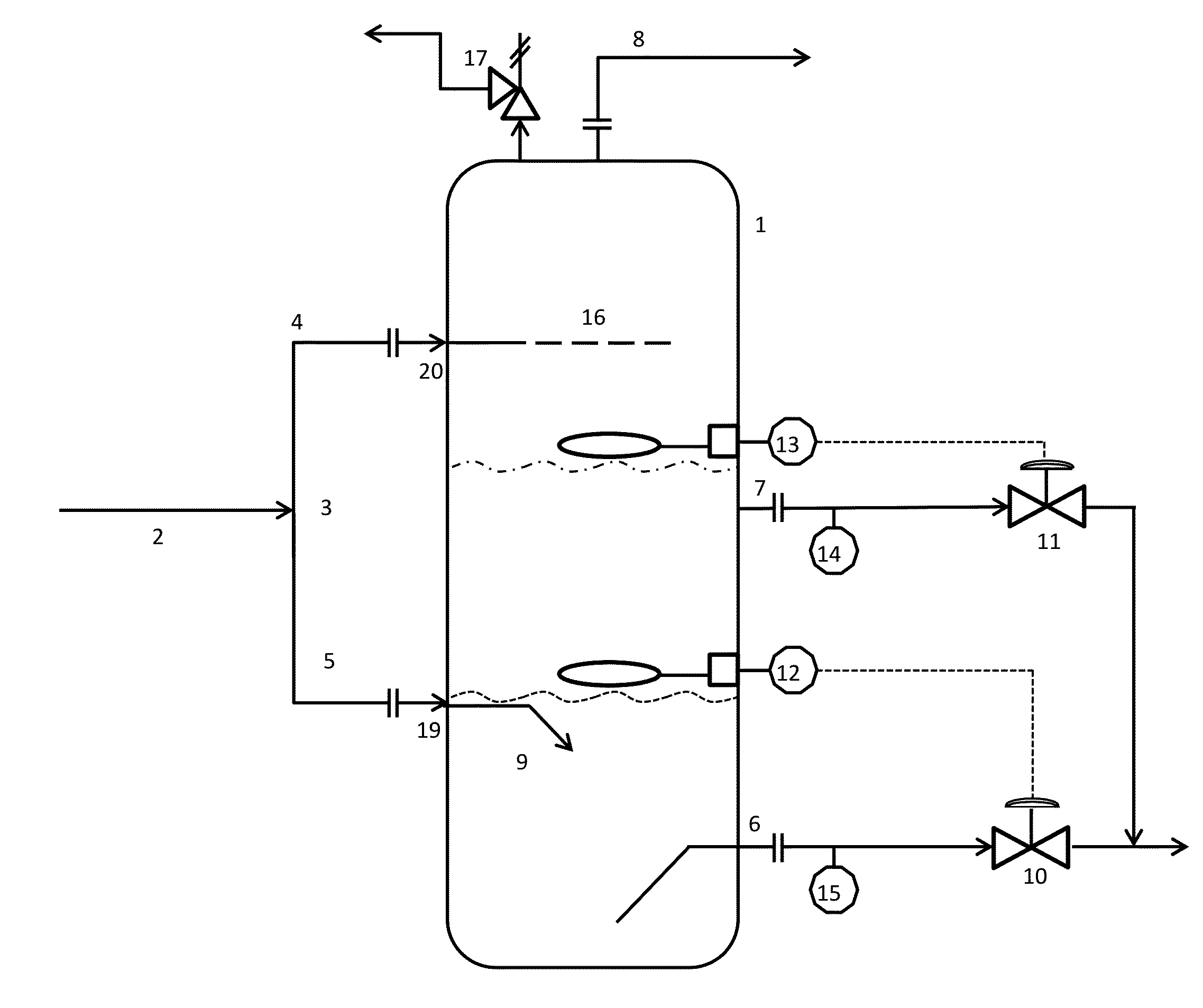
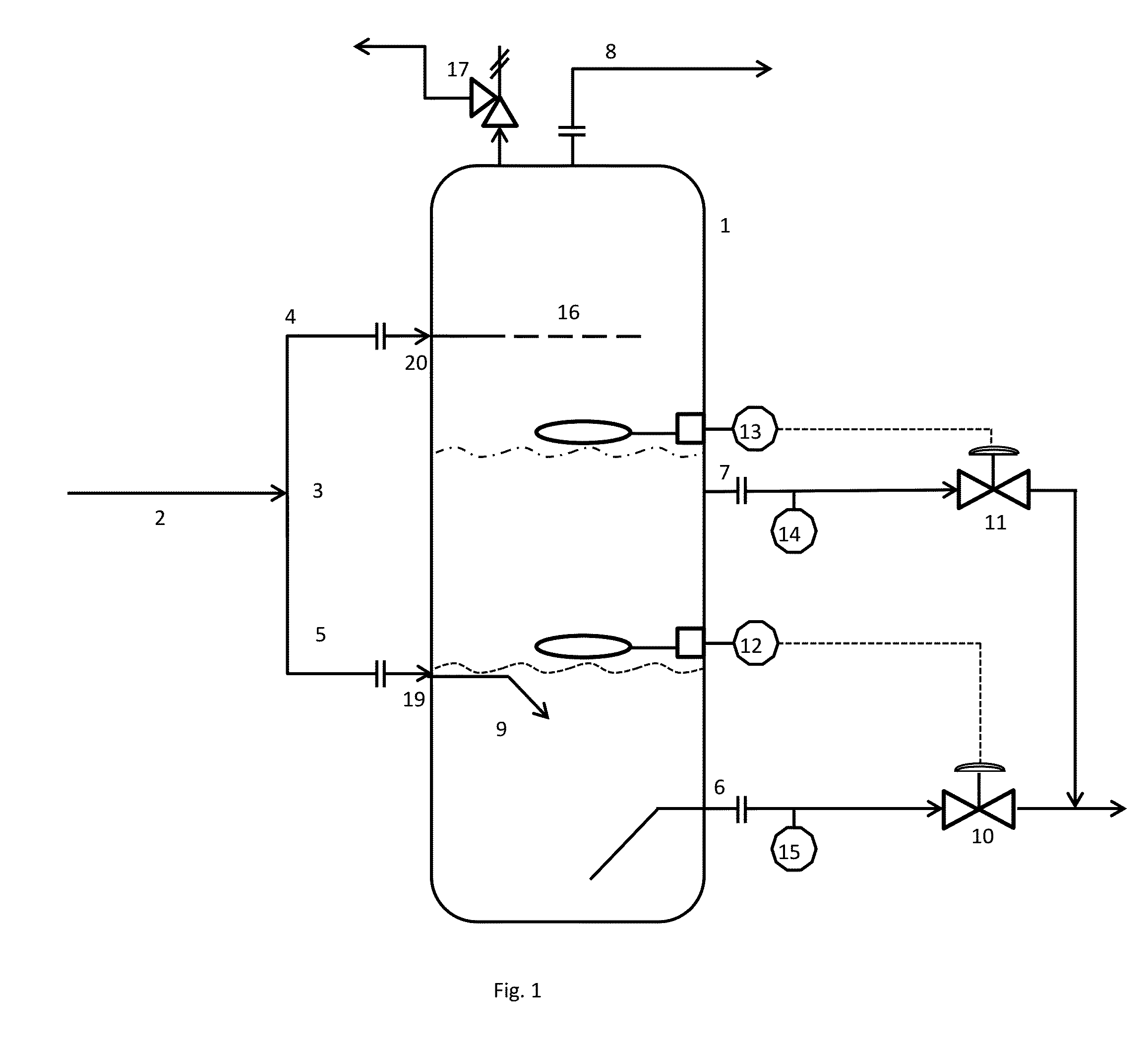
[0057]The separator device for three-phase fluids of the present invention, as shown in FIG. 1, comprises a vertical separator 1 for separating a three-phase feed fluid into its corresponding gas, oil and water phases, allowing for the extraction of the corresponding fluids from each one of said phases.

[0058]The three-phase feed fluid to be separated comes from a horizontal three-phase fluid feed line 2. Said horizontal three-phase fluid feed line 2, in proximity to the vertical separator 1, comprises a “T” joint 3, which divides the three-phase fluid feed flow into a first vertical ascending fluid flow feed line 4 and a second vertical descending fluid flow feed line 5. The first vertical ascending feed line 4 is connected in its upper portion to the vertical separator 1 by an inlet 20, while the second vertical descending feed line 5 is connected to the ...


PUM

PropertyMeasurementUnit
positive displacement flowaaaaaaaaaa
positive displacement flow meteraaaaaaaaaa
colorimetric analysisaaaaaaaaaa

Abstract

A new device and method for separating all phases of a three-phase fluid of the crude oil type, by means of a two-phase fluid separating device provided with a “T” joint for splitting the feed flow. The invention allows the conversion of two-phase separator into a three-phase fluid separating device, updating its functionality, increasing service life, using most of the original parts and components.

Description

FIELD OF THE INVENTION[0001]The present invention relates to a device for separating the phases of a three-phase fluid of the crude oil type, a method for separating the phases of said fluid, and a method for converting a two-phase fluid separating device into a three-phase fluid separating device.BACKGROUND OF THE INVENTION[0002]Crude oil and natural gas are usually obtained from underground formations, from which they are extracted through deep perforations. Generally, the fluid obtained from oil deposits consists of a mixture of oil, gas and brine.[0003]Once the crude oil is extracted, along with gas and water, it is sent to batteries or collecting stations where separation of the different fluids and measuring of the volume produced by the different wells are performed.[0004]Usually, two-phase separators are used for a first, gas-liquid separation, so the gas, after eventual dehydration and sweetening, can be sent for its utilization by means of gas pipelines, while the liquid p...

Claims


Application Information

Patent Timeline
Patent Type & Authority Applications(United States)
IPC IPC(8): B01D17/02B01D19/00
CPCB01D17/02B01D19/0073B01D19/0068B01D17/12B01D19/0036
Inventor ROSAS, RUBEN ORLANDO
Owner YPF SA
Why Eureka
Try Eureka