Hanger for axle/suspension systems

a technology for suspension systems and hangers, which is applied in the direction of suspension arms, pivoted suspensions, vehicle components, etc., can solve the problems of misalignment of the axle/suspension system, the pre-drilled openings of the hanger often do not align properly with the pre-drilled openings of the main and cross members of the frame, and the relative rough rid

Active Publication Date: 2016-09-22
HENDRICKSON USA L L C
View PDF1 Cites 4 Cited by
  • Summary
  • Abstract
  • Description
  • Claims
  • Application Information

AI Technical Summary

Benefits of technology

[0013]Objectives of the present invention include providing a hanger for axle / suspension systems that is free of multiple opening patterns previously required to fit multiple frame configurations.

Problems solved by technology

However, the spring suspension system resulted in a relatively rough ride to the cargo and did not equalize loads in all situations, thus creating the need for a frame design with soft ride characteristics and efficient load equalization characteristics.
However, because of tolerance stacks, the pre-drilled openings in the hanger often do not align properly with the pre-drilled openings in the main members and cross members of the frame.
As a result, urging or forcing the hanger openings and the main member and cross member openings to align with one another can create improper hanger spacing, which can in turn lead to misalignment of the axle / suspension system.
More specifically, misalignment of the axle / suspension system due to improper hanger spacing results in toe-in or toe-out conditions at the axle spindles of the axle / suspension system.
These toe-in or toe-out conditions at the axle spindles can in turn potentially contribute to irregular tire wear.
Axle / suspension systems that have less lateral compliance are especially susceptible to toe-in or toe-out conditions at the axle spindles due to improper or offset hanger spacing.
This method of installation assures proper hanger spacing, but can take significant time to complete because it takes significant man hours to form each of the matched-drilled openings in the main members and the cross members of the frame, thereby increasing manufacturing costs.
This requires the suspension supporting structure of the trailer to accommodate a different spacing for the self-steer suspension only, which no longer matches the remaining fixed suspensions on the trailer, therefore requiring many unique trailer structure components.

Method used


Image

  • Hanger for axle/suspension systems
  • Hanger for axle/suspension systems
  • Hanger for axle/suspension systems

Examples


Embodiment Construction

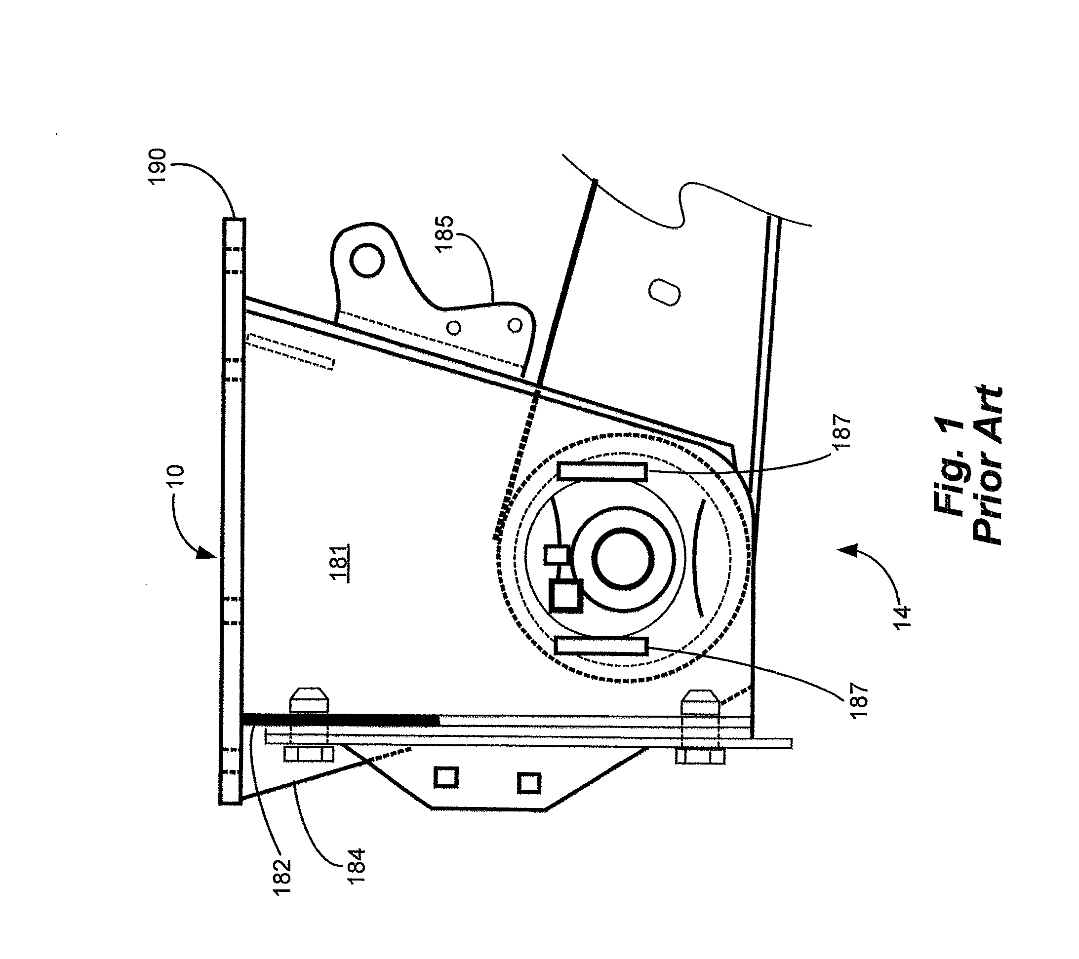
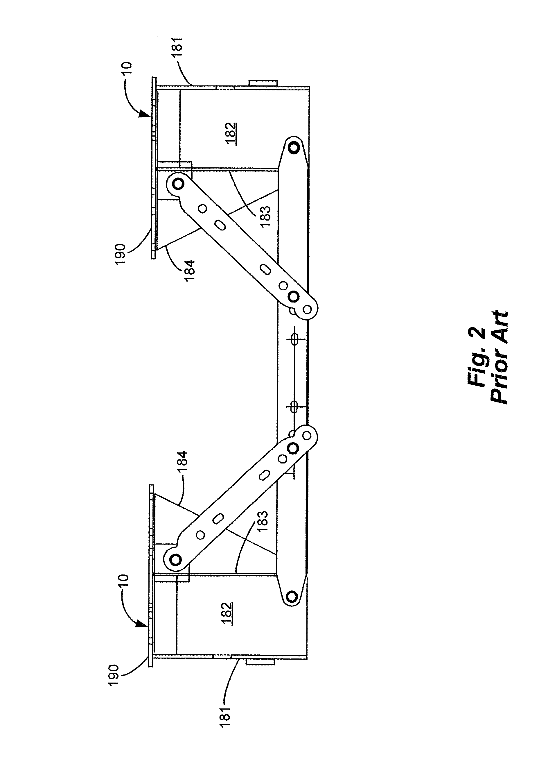
[0029]In order to better understand the structure, assembly and operation of the preferred embodiment hanger of the present invention for an axle / suspension system and frame, the structure, assembly and operation of a prior art bolt-on hanger will be described in detail below. A suspension assembly 14 (only a portion shown) of an axle / suspension system is shown in FIG. 1 pivotally attached to a prior art bolt-on hanger 10. With additional reference to FIGS. 2 and 3, hanger 10 includes a generally U-shaped cross section having an outboard wall 181, a front wall 182 and an inboard wall 183. A flange 184 extends inboard from the rear edge of inboard wall 183 of hanger 10 and is attached to a top plate 190. A shock mount 185 is attached to the rear surface of flange 184 by any suitable means, such as welding. A pair of aligned openings 186 (FIG. 3) are formed through outboard wall 181 and inboard wall 183 of hanger 10. A pair of alignment guides 187 (FIG. 1) are formed on the outboard s...


PUM


Abstract

A hanger for axle/suspension systems of a heavy-duty vehicle includes an outboard wall spaced apart from an inboard wall. The outboard wall is connected to the inboard wall via a front wall. The outboard wall and the inboard wall are formed with an aligned opening extending through the outboard wall and the inboard wall. A top plate connected to the inboard wall, the outboard wall and the front wall. The top plate is formed with at least one circular opening or laterally oriented oblong-round opening and at least one laterally slotted opening. A fastener is disposed through the at least one circular opening or oblong-round opening. A second fastener is disposed through the at least one laterally slotted opening for mounting the hanger to a frame of the heavy-duty vehicle.

Description

CROSS-REFERENCE TO RELATED APPLICATION[0001]This application claims the benefit of U.S. Provisional Patent Application Ser. No. 62 / 135,765, filed Mar. 20, 2015.BACKGROUND OF THE INVENTION[0002]1. Field of the Invention[0003]The invention relates generally to tractor-trailers and to frames and sub-frames for tractor-trailers. More particularly the invention is directed to a hanger that attaches to the frame of a tractor-trailer and which is used to mount the axle / suspension system to the frame. More specifically, the invention is directed to a hanger that includes a plurality of slotted openings for mounting the hanger to a main member of a frame of a heavy-duty vehicle and at least one circular or oblong-round opening for mounting the hanger to a cross member of the frame of the heavy-duty vehicle. The invention provides the ability to pre-drill the opening patterns on the frame at the trailer original equipment manufacturer, thereby eliminating and / or reducing the need for matched-...

Claims


Application Information

Patent Timeline
Patent Type & Authority Applications(United States)
IPC IPC(8): B60G1/00
CPCB60G1/00B60G2206/0112B60G2206/82B60G2204/15B60G7/008B62D21/11B60G2206/8207B60G2204/143B60G2204/4302B60G2206/601B60G7/02
Inventor MCCOMSEY, KEITH D.CARR, KIMM L.MUCKELRATH, BRETT L.
Owner HENDRICKSON USA L L C
Why Eureka
Try Eureka