Roller bearing, in particular for a mirror of a motor vehicle

Inactive Publication Date: 2016-09-22
AB SKF
View PDF15 Cites 2 Cited by
  • Summary
  • Abstract
  • Description
  • Claims
  • Application Information

AI Technical Summary

Benefits of technology

[0006]The present invention is intended to provide a roller bearing, in particular a wing mirro

Problems solved by technology

Before assembly of the mirror, there is a risk of accidental disassembly of the elements making up the roller bearing, for ex

Method used


Image

  • Roller bearing, in particular for a mirror of a motor vehicle
  • Roller bearing, in particular for a mirror of a motor vehicle
  • Roller bearing, in particular for a mirror of a motor vehicle

Examples


Example

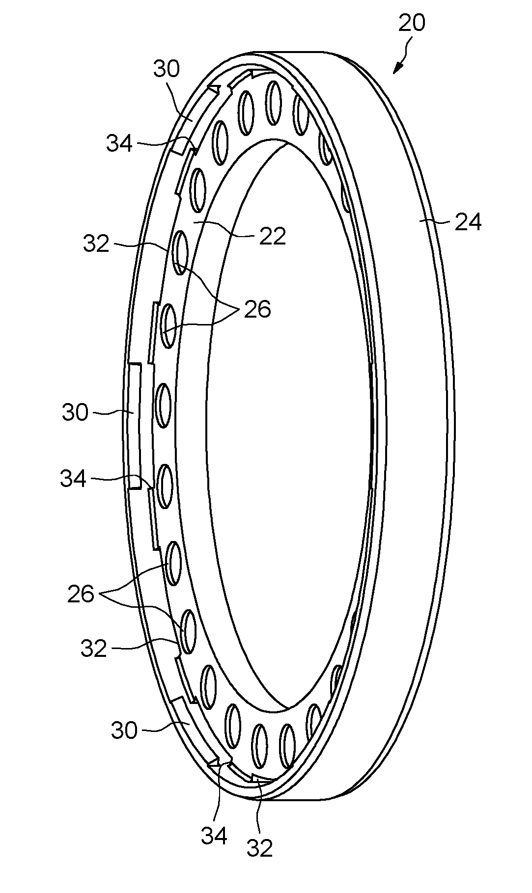
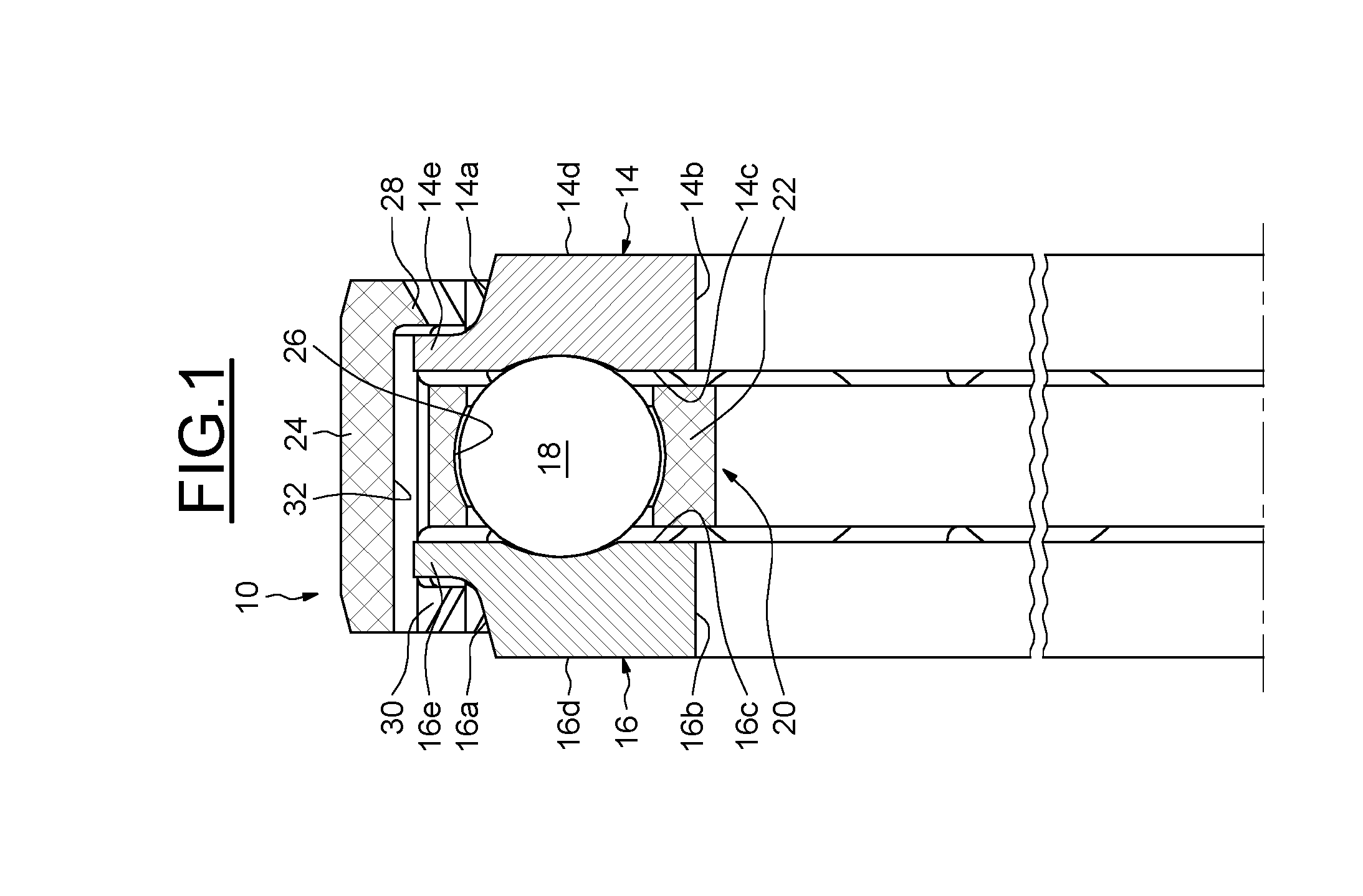
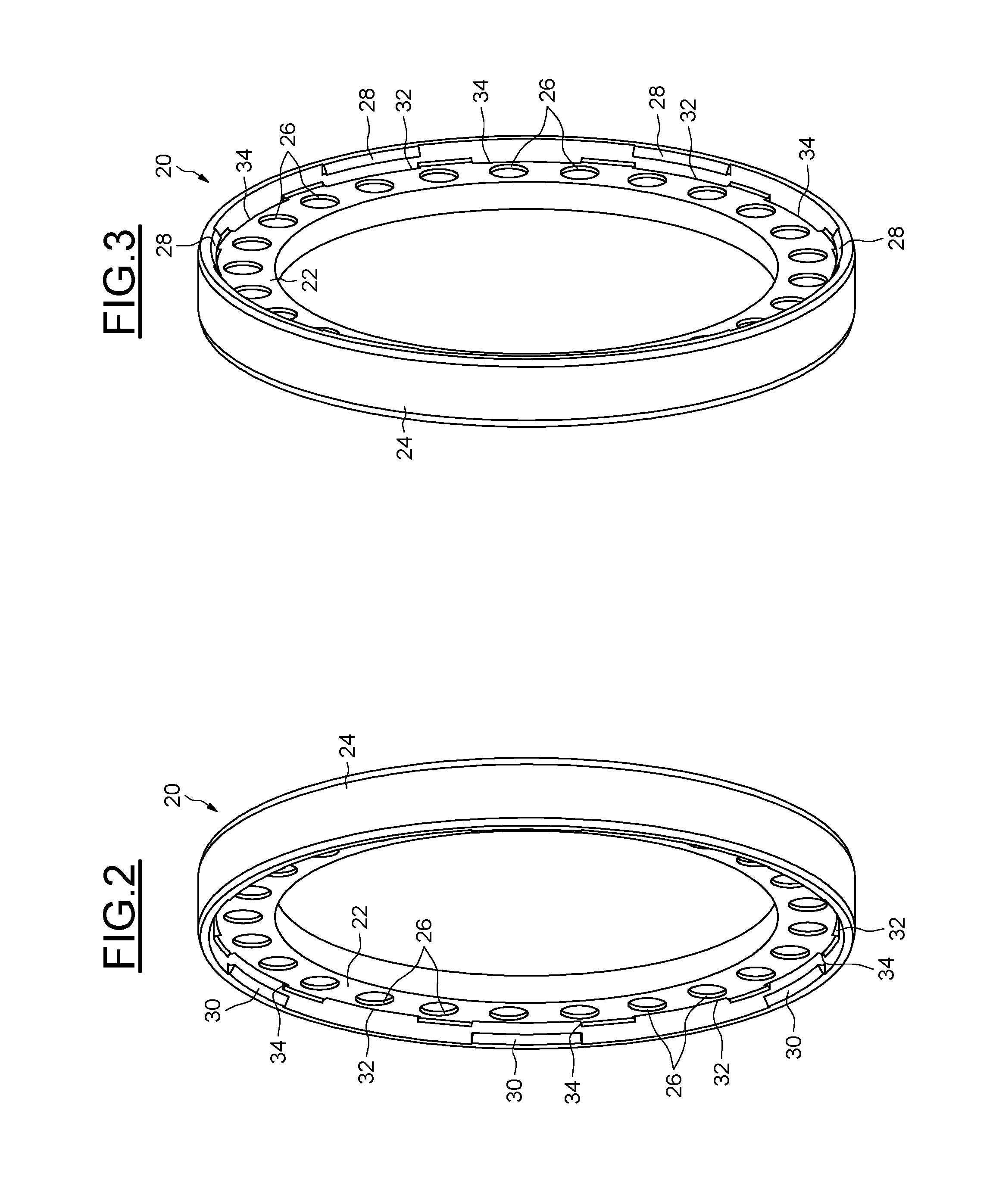
[0023]In FIG. 1, a roller bearing 10 with axis 12 includes a first ring 14, a second ring 16, a plurality of rolling elements 18, in this case balls arranged axially between the rings, and a cage 20 for maintaining the circumferential spacing of the rolling elements.

[0024]The rings 14, 16 are concentric. In the example embodiment shown, the rings are solid. “Solid ring” means a ring that is formed by machining tubes, bars or forged and / or rolled blanks with stock removal (turning, grinding).

[0025]The first ring 14 has a cylindrical outer surface 14a, a cylindrical bore 14b, two opposing radial front surfaces 14c, 14d axially delimiting the bore and the outer surface, and a race formed on the front surface 14c and having in cross section an internal concave profile adapted to the rolling elements 18, the race being oriented axially towards the inner ring 16. The first ring 14 also includes an annular projection 14e extending radially outwards from the outer surface 14a.

[0026]The sec...


PUM

PropertyMeasurementUnit
Circumferenceaaaaaaaaaa

Abstract

A roller bearing having a first ring, a second ring, at least one row of rolling elements arranged between the rings, and a cage for keeping the rolling elements circumferential in relation to one another. The cage includes first axial retaining means for the first ring and second axial retaining means for the second ring.

Description

CROSS REFERENCE TO RELATED APPLICATION[0001]This is a Non-Provisional Patent Application, filed under the Paris Convention, claiming the benefit of French (FR) Patent Application Number 1552229, filed on 18 Mar. 2015, which is incorporated herein by reference in its entirety.TECHNICAL FIELD OF THE INVENTION[0002]The present invention relates to the domain of roller bearings, in particular roller bearings used in wing mirrors on motor vehicles.BACKGROUND OF THE INVENTION[0003]Conventionally, such a bearing comprises first and second rings, a row of rolling elements arranged between the rings and a cage for maintaining the circumferential spacing of the rolling elements. Before assembly of the mirror, there is a risk of accidental disassembly of the elements making up the roller bearing, for example during storage, carriage or assembly.[0004]In another application, a roller bearing is known from patent applications FR-A1-2 806 135 and FR-A1-2 915 778 that is fitted with a cage for mai...

Claims


Application Information

Patent Timeline
IPC IPC(8): F16C33/38
CPCF16C33/3806F16C19/06F16C2326/01F16C2208/04F16C2208/60F16C33/3856F16C19/10
Inventor PERROTIN, THOMAS
Owner AB SKF
Why Eureka
Try Eureka